Dell MXG610s Fibre Channel Switch Module Installation Guide May 2018 - Page 22
Switch module monitoring, Port-side LEDs
 |
View all Dell MXG610s manuals
Add to My Manuals
Save this manual to your list of manuals |
Page 22 highlights
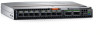
6 Switch module monitoring Topics: • Port-side LEDs • POST results • BOOT results • Diagnostic tests • Remove a license • Software upgrade or downgrade Port-side LEDs Each switch module uses bicolored external LEDs to indicate operation status. After you install the switch module in a blade server chassis I/O module, the LEDs become active. Figure 8. Switch module front panel LEDs 1 FC port 0 status LED 3 FC port 24 status LED 5 Module identification LED Table 4. Port-side LEDs LED Module power and status LED Module identification LED 22 Switch module monitoring 2 FC port 17 status LED 4 Module power status LED Description • Solid green-The switch is working correctly. • Blinking amber-The switch is working incorrectly. The temperature may be too high, a software error has occurred, or another error is discovered. • Off-There is no power supplied to the FC switch module. Reseat the module and ensure that the chassis power is on and it has adequate power for the I/O module. • Off-Module is not identified. • Blinking blue-Module is being identified.
-
 1
1 -
2
-
3
-
4
-
5
-
6
-
7
-
8
-
9
-
10
-
11
-
12
-
13
-
14
-
15
-
16
-
 17
17 -
 18
18 -
 19
19 -
 20
20 -
 21
21 -
 22
22 -
 23
23 -
 24
24 -
 25
25 -
 26
26 -
 27
27 -
28
-
29
-
30
-
31
-
32
-
33
-
34
-
35
-
36
-
37
-
38
-
39
-
40
-
41
-
42
-
43
-
44
-
45
 |
 |
