Dell MXG610s Fibre Channel Switch Module Installation Guide May 2018 - Page 16
Switch module orientation, If you use QSFP ports instead of SFP+ ports
 |
View all Dell MXG610s manuals
Add to My Manuals
Save this manual to your list of manuals |
Page 16 highlights
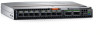
Figure 5. Switch module orientation 1 Backplane connectors 3 Switch module latch in open position 2 Switch module top view 3 Open the release lever, and slide the switch module into the blade server chassis slot completely. You hear a click when the switch module is locked in the blade server chassis I/O module bay. If the power is on in the blade server chassis, locking the switch module in the module bay provides power and turn-ons the switch module and the LEDs. The switch module then runs POSTs. These tests can take up to two minutes to complete. After the power/status LED light is steady green for at least two minutes, the module is ready to use. 4 Start from port 0, then port 17, and then the rest of the ports when cabling the SFP+ ports. If you use QSFP ports instead of SFP+ ports, transfer the port license from port 0 and 17 to the desired QSFP ports. The QSFP ports must be unused and no additional port licenses are available. Ports 0 and 17 are prelicensed at factory. You are now ready to insert more SFP+/QSFP optical transceivers, if needed. Be sure to use only Brocade-branded SFP+/QSFP optical transceivers. The FC switch module does not recognize unapproved products. Before you insert the transceivers and attach the cables, review the installation precautions and guidelines for SFP+/QSFP optical transceivers and cables. 16 Switch module installation overview
-
 1
1 -
2
-
3
-
4
-
5
-
6
-
7
-
8
-
9
-
10
-
 11
11 -
 12
12 -
 13
13 -
 14
14 -
 15
15 -
 16
16 -
 17
17 -
 18
18 -
 19
19 -
 20
20 -
 21
21 -
22
-
23
-
24
-
25
-
26
-
27
-
28
-
29
-
30
-
31
-
32
-
33
-
34
-
35
-
36
-
37
-
38
-
39
-
40
-
41
-
42
-
43
-
44
-
45
 |
 |
