Dell MXG610s Fibre Channel Switch Module Installation Guide May 2018 - Page 23
POST results, BOOT results, Diagnostic tests
 |
View all Dell MXG610s manuals
Add to My Manuals
Save this manual to your list of manuals |
Page 23 highlights
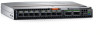
LED FC port status LED POST results Description • Both off-No light or signal carrier-no module, no cable-for the media interface • Solid amber-Receiving light or signal carrier, but not yet online • Slow flashing amber, 2-second intervals-Disabled; results of diagnostics or the portdisable command. • Fast flashing amber, 1/2-second intervals-Error occurred, fault with port. • Solid green-Online; connected with external device over cable • Slow flashing green, 2-second intervals-Online but segmented; Loopback cable or incompatible switch. • Fast flashing green, 1/2-second intervals-Internal loopback, diagnostic. • Flickering green-Online and frames flowing through the port. The power-on self-test (POST) system check performs each time you start up, reboot, or reset the switch module. During the POST, the LEDs activate in various indicator patterns. NOTE: The default POST diagnostic level is 0; therefore, no POST runs by default. To run the post, set the POST diagnostic level to a nonzero value before powering on the switch module. After installation, the chassis management application manages the switch module. For specific information about managing the switch module, see the documentation that comes with your blade server chassis. To determine whether POST completed successfully or whether any errors were detected: • Verify that the LEDs on the switch module indicate a healthy switch. If one or more LEDs do not display a healthy state, verify that the LEDs are not set to beacon. To verify the LED state, use the switchShow command or web Tools. • To verify that the switch module is working correctly, use the blade server management application. • Review the system log for errors. Any errors detected during POST are written to the system log. This log is accessible through the errShow command. BOOT results BOOT includes the following tasks after POST completes: • Performs universal port configuration • Initializes links • Analyzes the fabric. If any ports are connected to other switches, the switch participates in a fabric configuration. • Obtains a domain ID and assigns port addresses. • Constructs unicast routing tables. • Enables normal port operation. Diagnostic tests In addition to POST, the fabric OS includes diagnostic tests to help troubleshoot the hardware and firmware. These tests include internal connections and circuitry, fixed media, and the transceivers and cables in use. Switch module monitoring 23
-
 1
1 -
2
-
3
-
4
-
5
-
6
-
7
-
8
-
9
-
10
-
11
-
12
-
13
-
14
-
15
-
16
-
17
-
 18
18 -
 19
19 -
 20
20 -
 21
21 -
 22
22 -
 23
23 -
 24
24 -
 25
25 -
 26
26 -
 27
27 -
 28
28 -
29
-
30
-
31
-
32
-
33
-
34
-
35
-
36
-
37
-
38
-
39
-
40
-
41
-
42
-
43
-
44
-
45
 |
 |
