Dell MXG610s Fibre Channel Switch Module Installation Guide May 2018 - Page 17
Switch module replacement - manual
 |
View all Dell MXG610s manuals
Add to My Manuals
Save this manual to your list of manuals |
Page 17 highlights
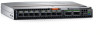
Switch module replacement If there is a switch module failure, you must remove and replace the switch module. NOTE: Before beginning this procedure, you must have a replacement switch module or filler blade available. Never leave the slot on the blade server chassis open for an extended time period. To maintain proper airflow, fill the slot with either a replacement switch module or filler blade. For more information about removing and replacing the switch module, see the blade server chassis operating manual. 1 Back up the switch module configuration to an FTP server using the configUpload command. The configUpload command uploads the switch module configuration to the server and makes it available for downloading to the replacement switch module if necessary. To ensure that a complete configuration is available for downloading to a replacement switch module, back up the configuration regularly. 2 Stop all activity requiring the ports the switch module uses. To verify that there is no activity, view the switch module LEDs. For details about port management, see your blade server chassis operating manual. 3 Disconnect all cables from the SFP+/QSFP optical transceivers. 4 Remove the SFP+ or QSFP optical transceivers from the switch module external ports. 5 Press the release latch, and gently pull the release lever out from the switch module. You can feel the switch module unseat and move out of the I/O module bay approximately 0.6 cm (0.25 in). The following shows the open and unlocked view of the release lever and release latch: Switch module installation overview 17
-
 1
1 -
2
-
3
-
4
-
5
-
6
-
7
-
8
-
9
-
10
-
11
-
 12
12 -
 13
13 -
 14
14 -
 15
15 -
 16
16 -
 17
17 -
 18
18 -
 19
19 -
 20
20 -
 21
21 -
 22
22 -
23
-
24
-
25
-
26
-
27
-
28
-
29
-
30
-
31
-
32
-
33
-
34
-
35
-
36
-
37
-
38
-
39
-
40
-
41
-
42
-
43
-
44
-
45
 |
 |
