Dell PowerEdge M620 Hardware Owner's Manual - Page 173
General Memory Module Installation Guidelines - PowerEdge M915
 |
View all Dell PowerEdge M620 manuals
Add to My Manuals
Save this manual to your list of manuals |
Page 173 highlights
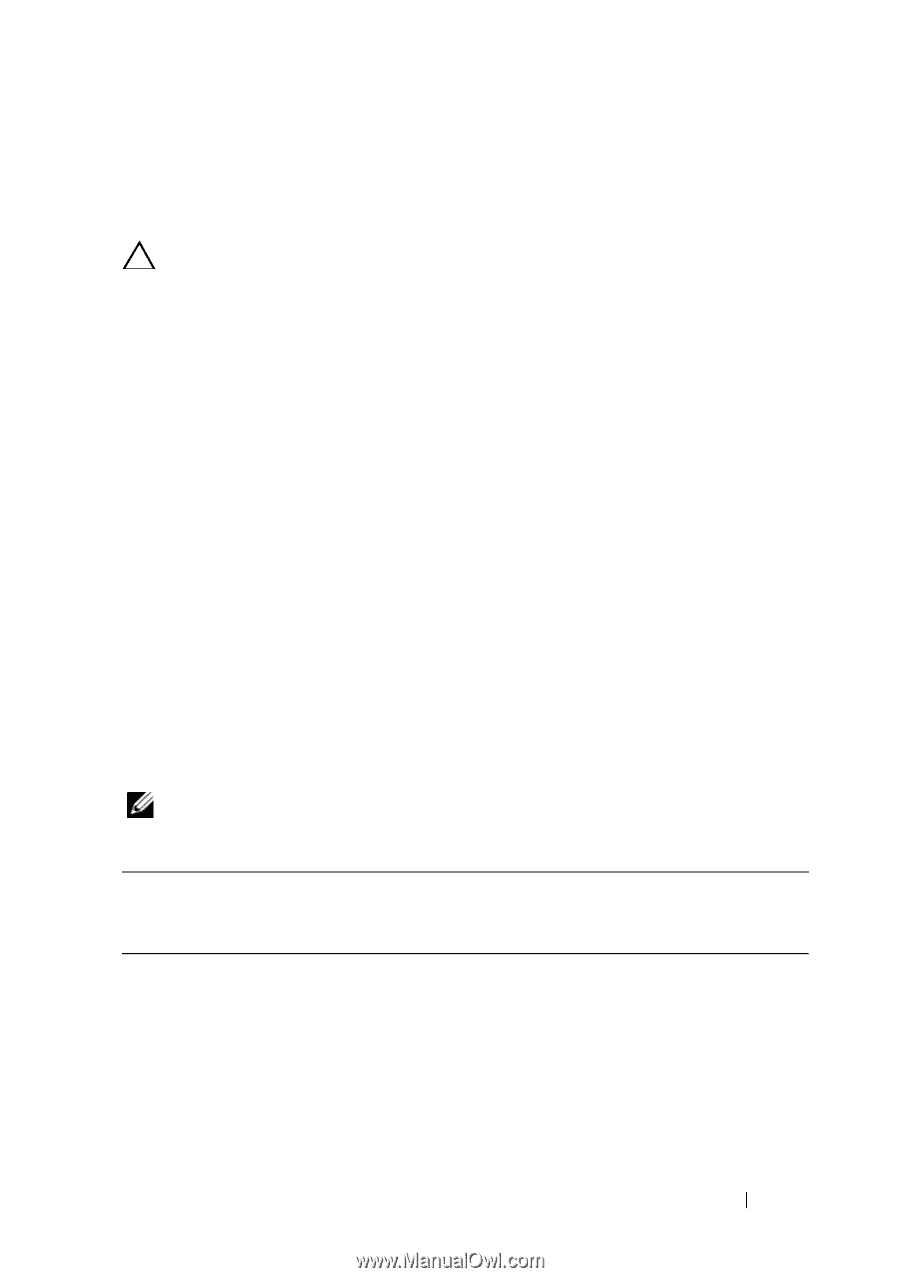
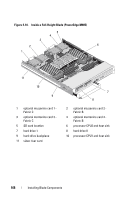
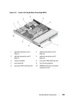
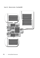
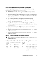
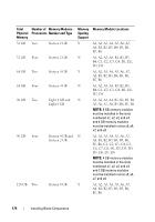
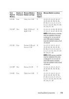
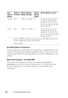
General Memory Module Installation Guidelines - PowerEdge M915 To ensure optimal performance of your system, observe the following guidelines when configuring your system memory: CAUTION: Memory module blanks must be installed in unoccupied memory sockets to maintain proper cooling airflow. • Memory modules must be installed in pairs, beginning with the first two sockets in each set of memory modules. These sockets are marked by white retention levers. • The memory configuration for each processor must be identical. • Memory modules must be identical in size, speed, and technology in lock-step pair (same colored levers). • If quad-rank memory modules are mixed with single- or dual-rank modules, the quad-rank modules must be installed in the sockets with the white release levers. • If pairs of memory modules of different sizes are installed, the larger capacity memory modules must be installed in the lower numbered slots. • Memory sparing is supported in a four-processor system only if 32 memory modules are installed. • Memory sparing is supported in a two-processor system only if 16 memory modules are installed. Table 3-1. Examples of PowerEdge M915 Memory Configurations NOTE: DIMMs A1-A8 are assigned to processor 1, DIMMs B1-B8 are assigned to processor 2, and so on. Total Physical Memory 8 GB 16 GB 16 GB Number of Memory Modules - Memory Processors Number and Type Sparing Support Two Eight 1 GB N Two Eight 2 GB N Four Sixteen 1 GB N Memory Module Locations A1, A2, A3, A4, B1, B2, B3, B4 A1, A2, A3, A4, B1, B2, B3, B4 A1, A2, A3, A4, B1, B2, B3, B4, C1, C2, C3, C4, D1, D2, D3, D4 Installing Blade Components 173
-
 1
1 -
2
-
3
-
4
-
5
-
6
-
7
-
8
-
9
-
10
-
11
-
12
-
13
-
14
-
15
-
16
-
17
-
18
-
19
-
20
-
21
-
22
-
23
-
24
-
25
-
26
-
27
-
28
-
29
-
30
-
31
-
32
-
33
-
34
-
35
-
36
-
37
-
38
-
39
-
40
-
41
-
42
-
43
-
44
-
45
-
46
-
47
-
48
-
49
-
50
-
51
-
52
-
53
-
54
-
55
-
56
-
57
-
58
-
59
-
60
-
61
-
62
-
63
-
64
-
65
-
66
-
67
-
68
-
69
-
70
-
71
-
72
-
73
-
74
-
75
-
76
-
77
-
78
-
79
-
80
-
81
-
82
-
83
-
84
-
85
-
86
-
87
-
88
-
89
-
90
-
91
-
92
-
93
-
94
-
95
-
96
-
97
-
98
-
99
-
100
-
101
-
102
-
103
-
104
-
105
-
106
-
107
-
108
-
109
-
110
-
111
-
112
-
113
-
114
-
115
-
116
-
117
-
118
-
119
-
120
-
121
-
122
-
123
-
124
-
125
-
126
-
127
-
128
-
129
-
130
-
131
-
132
-
133
-
134
-
135
-
136
-
137
-
138
-
139
-
140
-
141
-
142
-
143
-
144
-
145
-
146
-
147
-
148
-
149
-
150
-
151
-
152
-
153
-
154
-
155
-
156
-
157
-
158
-
159
-
160
-
161
-
162
-
163
-
164
-
165
-
166
-
167
-
 168
168 -
 169
169 -
 170
170 -
 171
171 -
 172
172 -
 173
173 -
 174
174 -
 175
175 -
 176
176 -
 177
177 -
 178
178 -
179
-
180
-
181
-
182
-
183
-
184
-
185
-
186
-
187
-
188
-
189
-
190
-
191
-
192
-
193
-
194
-
195
-
196
-
197
-
198
-
199
-
200
-
201
-
202
-
203
-
204
-
205
-
206
-
207
-
208
-
209
-
210
-
211
-
212
-
213
-
214
-
215
-
216
-
217
-
218
-
219
-
220
-
221
-
222
-
223
-
224
-
225
-
226
-
227
-
228
-
229
-
230
-
231
-
232
-
233
-
234
-
235
-
236
-
237
-
238
-
239
-
240
-
241
-
242
-
243
-
244
-
245
-
246
-
247
-
248
-
249
-
250
-
251
-
252
-
253
-
254
-
255
-
256
-
257
-
258
-
259
-
260
-
261
-
262
-
263
-
264
-
265
-
266
-
267
-
268
-
269
-
270
-
271
-
272
-
273
-
274
-
275
-
276
-
277
-
278
-
279
-
280
-
281
-
282
-
283
-
284
-
285
-
286
-
287
-
288
-
289
-
290
-
291
-
292
-
293
-
294
-
295
-
296
-
297
-
298
-
299
-
300
-
301
-
302
-
303
-
304
-
305
-
306
-
307
-
308
-
309
-
310
-
311
-
312
-
313
-
314
-
315
-
316
-
317
-
318
-
319
-
320
-
321
-
322
-
323
-
324
-
325
-
326
-
327
-
328
-
329
-
330
-
331
-
332
-
333
-
334
-
335
-
336
-
337
-
338
-
339
-
340
-
341
-
342
-
343
-
344
-
345
-
346
-
347
-
348
-
349
-
350
-
351
-
352
-
353
-
354
-
355
-
356
-
357
-
358
-
359
-
360
-
361
-
362
-
363
-
364
-
365
-
366
-
367
-
368
 |
 |