| Section |
Page |
| Dell PowerEdge Modular Systems |
1 |
| Contents |
3 |
| About Your System |
13 |
| Accessing System Features During Start-up |
13 |
| System Overview |
14 |
| System Control Panel Features |
16 |
| LCD Module |
18 |
| LCD Module Features |
19 |
| Using the LCD Module Menus |
19 |
| Configuration Wizard |
20 |
| Main Menu |
21 |
| LCD Setup Menu |
21 |
| Server Menu |
21 |
| Enclosure Menu |
21 |
| Blade Features |
22 |
| Using USB Diskette or USB DVD/CD Drives |
31 |
| Hard-Drive Features |
31 |
| Back-Panel Features |
34 |
| Power Supply Indicator |
36 |
| Fan Module Indicators |
37 |
| Identifying Midplane Version |
38 |
| iKVM Module |
41 |
| Tiering the Avocent iKVM Switch From an Analog KVM Switch |
44 |
| Tiering the Avocent iKVM Switch From a Digital KVM Switch |
46 |
| Resynchronizing the Server List at the Remote Client Workstation |
47 |
| CMC Module |
48 |
| I/O Connectivity |
52 |
| Guidelines for Installing I/O Modules |
52 |
| General I/O Module Configuration Guidelines |
52 |
| Fabric A |
52 |
| Fabric B |
53 |
| Fabric C |
53 |
| Port Auto-Disablement in Quad-Port Network Daughter Card (PowerEdge M710HD Only) |
53 |
| Mezzanine Cards |
55 |
| PowerEdge M610x Only |
55 |
| Full-Height Blades |
55 |
| Half-Height Blades |
55 |
| I/O Module Port Mapping |
58 |
| Full-Height Blades |
58 |
| Standard LOM (Dual-Port) Mapping |
58 |
| Dual-Port Mezzanine Cards |
59 |
| Half-Height Blades |
66 |
| Standard LOM (Dual-Port) and Network Daughter Card (Quad-Port) Mapping |
66 |
| Dual-Port Mezzanine Cards |
66 |
| Dell PowerConnect-KR 8024-k Switch |
69 |
| Dell M8428-k 10 Gb Converged Network Switch |
71 |
| Mellanox M3601Q QDR Infiniband Switch I/O Module |
73 |
| Mellanox M2401G Infiniband Switch I/O Module |
74 |
| Cisco SFS M7000e Infiniband Switch Module |
75 |
| Cisco Ethernet Switch |
77 |
| PowerConnect M6348 1 Gb Ethernet Switch I/O Module |
79 |
| PowerConnect M8024 10 Gb Ethernet Switch I/O Module |
81 |
| PowerConnect M6220 Ethernet Switch Module |
83 |
| Dell 10 GbE KR Pass-Through I/O Module |
85 |
| Dell 8/4 Gbps Fibre Channel Pass-Through I/O Module |
86 |
| 10 Gb Ethernet Pass-Through Module II |
88 |
| 10 Gb Ethernet Pass-Through I/O Module |
90 |
| 4 Gbps Fibre Channel Pass-Through Module |
92 |
| Brocade M5424 FC8 I/O Module |
95 |
| Brocade M4424 SAN I/O Module |
98 |
| 10/100/1000 Mb Ethernet Pass-Through Module |
101 |
| LCD Status Messages |
103 |
| Viewing Status Messages |
103 |
| Removing LCD Status Messages |
103 |
| System Messages |
115 |
| Warning Messages |
134 |
| Diagnostics Messages |
135 |
| Alert Messages |
135 |
| Using the System Setup Program and UEFI Boot Manager |
137 |
| Choosing the System Boot Mode |
137 |
| Entering the System Setup Program |
138 |
| Responding to Error Messages |
138 |
| Using the System Setup Program Navigation Keys |
138 |
| System Setup Options |
139 |
| Memory Settings Screen |
140 |
| Processor Settings Screen |
141 |
| SATA Settings Screen (PowerEdge M610, M610x) |
143 |
| Boot Settings Screen |
143 |
| Integrated Devices Screen |
144 |
| PCI IRQ Assignments Screen |
146 |
| Serial Communication Screen |
146 |
| Power Management Screen (PowerEdge M915, M910, M710, M710HD, M610 and M610x Only) |
147 |
| System Security Screen |
148 |
| Exit Screen |
149 |
| Entering the UEFI Boot Manager |
150 |
| UEFI Boot Manager Screen |
150 |
| UEFI Boot Settings Screen |
150 |
| System Utilities Screen |
151 |
| System and Setup Password Features |
151 |
| Using the System Password |
151 |
| Assigning a System Password |
151 |
| Using Your System Password to Secure Your System |
152 |
| Changing an Existing System Password |
153 |
| Using the Setup Password |
153 |
| Assigning a Setup Password |
153 |
| Operating With a Setup Password Enabled |
154 |
| Deleting or Changing an Existing Setup Password |
154 |
| Installing Blade Components |
155 |
| Recommended Tools |
155 |
| Removing and Installing a Blade |
155 |
| Removing a Blade |
155 |
| Installing a Blade |
158 |
| Removing and Installing a Blade Blank |
158 |
| Removing a Blade Blank |
158 |
| Installing a Blade Blank |
159 |
| Opening and Closing the Blade |
159 |
| Opening the Blade |
159 |
| Closing the Blade |
161 |
| Inside the System |
162 |
| System Memory |
171 |
| System Memory - PowerEdge M915 |
171 |
| General Memory Module Installation Guidelines - PowerEdge M915 |
173 |
| Non-Optimal Memory Configurations |
176 |
| Memory Sparing Support - PowerEdge M915 |
176 |
| System Memory - PowerEdge M910 |
177 |
| General Memory Module Installation Guidelines - PowerEdge M910 |
179 |
| Non-Optimal Memory Configurations |
181 |
| Memory Sparing Support - PowerEdge M910 |
181 |
| System Memory - PowerEdge M905 |
181 |
| General Memory Module Installation Guidelines - PowerEdge M905 |
182 |
| Non-Optimal Memory Configurations |
184 |
| Memory Sparing Support - PowerEdge M905 |
184 |
| System Memory - PowerEdge M805 |
184 |
| General Memory Module Installation Guidelines - PowerEdge M805 |
185 |
| Non-Optimal Memory Configurations |
187 |
| Memory Sparing Support - PowerEdge M805 |
187 |
| System Memory - PowerEdge M710 |
188 |
| General Memory Module Installation Guidelines - PowerEdge M710 |
190 |
| Advanced ECC Mode Support - PowerEdge M710 |
190 |
| Memory Mirroring Support - PowerEdge M710 |
190 |
| Independent Channel Mode (Optimizer Mode) - PowerEdge M710 |
191 |
| System Memory - PowerEdge M710HD |
194 |
| General Memory Module Installation Guidelines - PowerEdge M710HD |
195 |
| Advanced ECC Mode Support - PowerEdge M710HD |
195 |
| Memory Mirroring Support - PowerEdge M710HD |
195 |
| Memory Sparing Support - PowerEdge M710HD |
196 |
| Independent Channel Mode (Optimizer Mode) - PowerEdge M710HD |
196 |
| System Memory - PowerEdge M610/M610x |
199 |
| General Memory Module Installation Guidelines - PowerEdge M610/M610x |
200 |
| Advanced ECC Mode Support - PowerEdge M610/M610x |
201 |
| Memory Mirroring Support - PowerEdge M610/M610x |
201 |
| Independent Channel Mode (Optimizer Mode) - PowerEdge M610/M610x |
202 |
| System Memory - PowerEdge M605 |
204 |
| General Memory Module Installation Guidelines - PowerEdge M605 |
205 |
| Single-Processor Memory Configurations |
206 |
| Dual-Processor Memory Configurations |
207 |
| Non-Optimal Memory Configurations |
208 |
| Memory Sparing Support - PowerEdge M605 |
208 |
| System Memory - PowerEdge M600 |
210 |
| General Memory Module Installation Guidelines - PowerEdge M600 |
211 |
| Non-Optimal Memory Configurations |
212 |
| Memory Sparing Support - PowerEdge M600 |
212 |
| Memory Mirroring Support - PowerEdge M600 |
212 |
| Installing Memory Modules |
213 |
| Removing Memory Modules |
214 |
| Mezzanine Interface Card (PowerEdge M610x Only) |
215 |
| Removing the Mezzanine Interface Card |
215 |
| Installing the Mezzanine Interface Card |
217 |
| I/O Module Mezzanine Cards |
217 |
| Mezzanine Card Installation Guidelines |
218 |
| Full-Height Blades |
218 |
| Half-Height Blades |
219 |
| Installing a Mezzanine Card |
219 |
| Removing a Mezzanine Card |
222 |
| SD Card |
223 |
| PowerEdge M905 and M805 |
223 |
| PowerEdge M915, M910, M710, M710HD, M610, and M610x |
224 |
| SD vFlash Card (PowerEdge M915, M910, M710, M710HD, M610, and M610x Only) |
225 |
| RAID Battery |
226 |
| Removing a RAID Battery |
226 |
| Installing the RAID Battery |
231 |
| Integrated NIC Hardware Key |
232 |
| Internal USB Key (PowerEdge M915, M910, M710, M710HD, M610, and M610x Only) |
232 |
| Network Daughter Card/LOM Riser Card (PowerEdge M915 and M710HD Only) |
233 |
| Removing the LOM Riser Card |
233 |
| Installing the LOM Riser Card |
234 |
| Expansion Cards and Expansion-Card Riser (PowerEdge M610x Only) |
235 |
| Expansion Card Installation Guidelines |
235 |
| Installing an Expansion Card |
236 |
| Removing an Expansion Card |
238 |
| Expansion-Card Riser (PowerEdge M610x Only) |
239 |
| Removing the Expansion-Card Riser |
239 |
| Installing the Expansion-Card Riser |
243 |
| Processors |
243 |
| Processor Installation Guidelines |
243 |
| PowerEdge M915 System |
243 |
| PowerEdge M910 System |
243 |
| PowerEdge M905 System |
243 |
| PowerEdge M805 System |
244 |
| PowerEdge M710, M710HD, M610, M610x, and M600 Systems |
244 |
| PowerEdge M605 System |
244 |
| Removing a Processor |
244 |
| Installing a Processor |
259 |
| FlexMem Bridge (PowerEdge M910 Only) |
261 |
| Removing a FlexMem Bridge |
261 |
| Installing a FlexMem Bridge |
261 |
| HT Bridge Card (PowerEdge M905 Only) |
262 |
| Removing an HT Bridge Card |
262 |
| Installing an HT Bridge Card |
264 |
| Blade System Board NVRAM Backup Battery |
265 |
| Removing and Installing the NVRAM Backup Battery |
265 |
| Hard Drives |
267 |
| Hard Drive Installation Guidelines |
267 |
| Installing a Hard Drive |
267 |
| Removing a Hard Drive |
269 |
| Shutdown Procedure for Servicing a Hard Drive |
269 |
| Configuring the Boot Drive |
269 |
| Removing a Hard Drive From a Hard-Drive Carrier |
269 |
| Installing a Hard Drive in a Hard-Drive Carrier |
270 |
| Video Controller (PowerEdge M905, M805, M605, and M600 Only) |
272 |
| Hard-Drive Backplane |
274 |
| Blade System Board |
276 |
| Removing the System Board |
276 |
| Installing the System Board |
280 |
| Storage Controller Card |
281 |
| Removing the Storage Controller Board |
281 |
| Installing the Storage Controller Board |
282 |
| Midplane Interface Card (PowerEdge M610x) |
283 |
| Removing the Midplane Interface Card |
283 |
| Installing the Midplane Interface Card |
285 |
| Installing Enclosure Components |
287 |
| Power Supply Modules |
287 |
| System Power Guidelines |
287 |
| Power Supply Blanks |
288 |
| Removing a Power Supply Module |
288 |
| Installing a Power Supply Module |
291 |
| Fan Modules |
291 |
| Removing a Fan Module |
291 |
| Installing a Fan Module |
292 |
| CMC Module |
293 |
| Removing a CMC Module |
293 |
| Installing an SD Card in the CMC Module |
294 |
| Installing a CMC Module |
295 |
| iKVM Module |
296 |
| Removing an iKVM Module |
296 |
| Installing an iKVM Module |
296 |
| I/O Modules |
296 |
| Removing an I/O Module |
296 |
| Installing an I/O Module |
298 |
| Enclosure Bezel |
298 |
| Removing the Enclosure Bezel |
298 |
| Installing the Enclosure Bezel |
299 |
| Enclosure Midplane |
300 |
| Installing the Midplane and Front Module Cage Assembly |
302 |
| Enclosure Control Panel Assembly |
303 |
| Removing the Enclosure Control Panel |
303 |
| Installing the Enclosure Control Panel |
305 |
| LCD Module |
305 |
| Removing the LCD Module |
305 |
| Installing the LCD Module |
307 |
| Troubleshooting Your System |
309 |
| Safety First-For You and Your System |
309 |
| Start-Up Routine |
309 |
| Checking the Equipment |
310 |
| Troubleshooting External Connections |
310 |
| Troubleshooting Video |
310 |
| Troubleshooting the Keyboard |
311 |
| Troubleshooting the Mouse |
311 |
| Troubleshooting USB Devices |
312 |
| Responding to a Systems Management Alert Message |
312 |
| Troubleshooting a Wet Enclosure |
312 |
| Troubleshooting a Damaged Enclosure |
313 |
| Troubleshooting Enclosure Components |
314 |
| Troubleshooting Power Supply Modules |
314 |
| Troubleshooting Fan Modules |
315 |
| Troubleshooting the CMC Module |
315 |
| Troubleshooting the iKVM Module |
317 |
| Problem: |
317 |
| Likely Cause and Solution: |
317 |
| Example: |
317 |
| Solution: |
317 |
| Troubleshooting a Network Switch Module |
318 |
| Troubleshooting Blade Components |
319 |
| Troubleshooting Blade Memory |
319 |
| Troubleshooting Hard Drives |
320 |
| Troubleshooting Expansion Cards |
321 |
| Troubleshooting Processors |
322 |
| Troubleshooting the Blade Board |
323 |
| Troubleshooting the NVRAM Backup Battery |
324 |
| Running System Diagnostics |
325 |
| Dell PowerEdge Diagnostics |
325 |
| System Diagnostics Features |
325 |
| When to Use the System Diagnostics |
326 |
| Running the System Diagnostics |
326 |
| Running the Embedded System Diagnostics |
326 |
| From a USB Flash Drive |
327 |
| System Diagnostics Testing Options |
328 |
| Using the Advanced Testing Options |
329 |
| Error Messages |
329 |
| System Board Information |
331 |
| Blade System Board Jumper Settings |
331 |
| PowerEdge M915 Jumper Settings |
331 |
| PowerEdge M910 Jumper Settings |
332 |
| PowerEdge M905 Jumper Settings |
332 |
| PowerEdge M805 Jumper Settings |
333 |
| PowerEdge M710 Jumper Settings |
334 |
| PowerEdge M710HD Jumper Settings |
335 |
| PowerEdge M610/M610x Jumper Settings |
336 |
| PowerEdge M600 Jumper Settings |
337 |
| System Board Connectors |
338 |
| PowerEdge M915 System Board |
338 |
| PowerEdge M910 System Board |
340 |
| PowerEdge M905 System Board |
342 |
| PowerEdge M805 System Board |
344 |
| PowerEdge M710 System Board |
346 |
| PowerEdge M710HD System Board |
348 |
| PowerEdge M610 System Board |
349 |
| PowerEdge M610x System Board |
350 |
| PowerEdge M610x Midplane Interface Card |
352 |
| PowerEdge M610x Expansion-Card Riser |
353 |
| PowerEdge M610x Mezzanine Interface Card |
354 |
| PowerEdge M605 System Board |
355 |
| PowerEdge M600 System Board |
357 |
| Disabling a Forgotten Password |
358 |
| Getting Help |
361 |
| Contacting Dell |
361 |
 1
1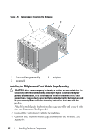 302
302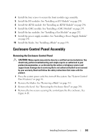 303
303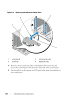 304
304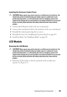 305
305 306
306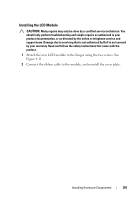 307
307 308
308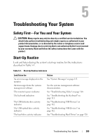 309
309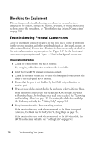 310
310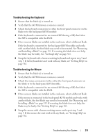 311
311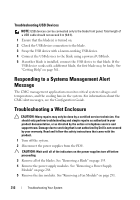 312
312