Dell PowerEdge R760 Installation and Service Manual - Page 13
Rear view of the system
 |
View all Dell PowerEdge R760 manuals
Add to My Manuals
Save this manual to your list of manuals |
Page 13 highlights
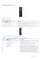
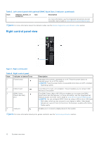
Rear view of the system Figure 8. Rear view of the system Table 5. Rear view of the system Item Ports, panels, or slots Icon 1 PCIe expansion card riser 1 N/A (slot 1 and slot 2) 2 BOSS module N/A 3 PCIe expansion card riser 2 N/A (slot 3 and slot 6) 4 PCIe expansion card riser 3 N/A (slot 4 and slot 5) 5 VGA port 6 PCIe expansion card riser 4 N/A (slot 7 and slot 8) 7 Power supply unit (PSU2) 8 USB 2.0 port 9 USB 3.0 port 10 Dedicated iDRAC9 Ethernet port 11 System Identification (ID) button Description The expansion card riser enables you to connect PCI Express expansion cards. For more information , see the Expansion card installation guidelines section. BOSS module for internal system boot. The expansion card riser enables you to connect PCI Express expansion cards. For more information , see the Expansion card installation guidelines section. The expansion card riser enables you to connect PCI Express expansion cards. For more information , see the Expansion card installation guidelines section. Enables you to connect a display device to the system. The expansion card riser enables you to connect PCI Express expansion cards. For more information , see the Expansion card installation guidelines section. PSU2 is the secondary PSU of the system. The USB port is 4-pin, 2.0-compliant. This port enables you to connect USB devices to the system. The USB port is 9-pin and 3.0-compliant. This port enables you to connect USB devices to the system. Enables you to remotely access iDRAC. For more information, see the Integrated Dell Remote Access Controller User's Guide at www.dell.com/poweredgemanuals. The System Identification (ID) button is available on the front and back of the system. Press the button to identify a system in a rack by turning on the system ID button. You can also use the system ID button to reset iDRAC and to access BIOS using the step through mode. When pressed, the system ID LED in the back panel blinks until either the front or rear button is pressed again. Press the button to toggle between on or off mode. System overview 13
-
 1
1 -
2
-
3
-
4
-
5
-
6
-
7
-
 8
8 -
 9
9 -
 10
10 -
 11
11 -
 12
12 -
 13
13 -
 14
14 -
 15
15 -
 16
16 -
 17
17 -
 18
18 -
19
-
20
-
21
-
22
-
23
-
24
-
25
-
26
-
27
-
28
-
29
-
30
-
31
-
32
-
33
-
34
-
35
-
36
-
37
-
38
-
39
-
40
-
41
-
42
-
43
-
44
-
45
-
46
-
47
-
48
-
49
-
50
-
51
-
52
-
53
-
54
-
55
-
56
-
57
-
58
-
59
-
60
-
61
-
62
-
63
-
64
-
65
-
66
-
67
-
68
-
69
-
70
-
71
-
72
-
73
-
74
-
75
-
76
-
77
-
78
-
79
-
80
-
81
-
82
-
83
-
84
-
85
-
86
-
87
-
88
-
89
-
90
-
91
-
92
-
93
-
94
-
95
-
96
-
97
-
98
-
99
-
100
-
101
-
102
-
103
-
104
-
105
-
106
-
107
-
108
-
109
-
110
-
111
-
112
-
113
-
114
-
115
-
116
-
117
-
118
-
119
-
120
-
121
-
122
-
123
-
124
-
125
-
126
-
127
-
128
-
129
-
130
-
131
-
132
-
133
-
134
-
135
-
136
-
137
-
138
-
139
-
140
-
141
-
142
-
143
-
144
-
145
-
146
-
147
-
148
-
149
-
150
-
151
-
152
-
153
-
154
-
155
-
156
-
157
-
158
-
159
-
160
-
161
-
162
-
163
-
164
-
165
-
166
-
167
-
168
-
169
-
170
-
171
-
172
-
173
-
174
-
175
-
176
-
177
-
178
-
179
-
180
-
181
-
182
-
183
-
184
-
185
-
186
-
187
-
188
-
189
-
190
-
191
-
192
-
193
-
194
-
195
-
196
-
197
-
198
-
199
-
200
-
201
-
202
-
203
-
204
-
205
-
206
-
207
-
208
-
209
-
210
-
211
-
212
-
213
-
214
-
215
-
216
-
217
-
218
-
219
-
220
-
221
-
222
-
223
-
224
-
225
-
226
-
227
-
228
-
229
-
230
-
231
-
232
-
233
-
234
-
235
-
236
-
237
-
238
-
239
-
240
-
241
-
242
-
243
-
244
-
245
-
246
-
247
-
248
-
249
-
250
-
251
-
252
-
253
-
254
-
255
-
256
-
257
-
258
-
259
-
260
-
261
-
262
-
263
-
264
-
265
-
266
-
267
-
268
-
269
-
270
-
271
-
272
-
273
-
274
-
275
-
276
-
277
-
278
-
279
-
280
-
281
-
282
-
283
-
284
-
285
-
286
-
287
-
288
-
289
-
290
-
291
-
292
-
293
-
294
-
295
-
296
-
297
-
298
-
299
-
300
-
301
-
302
-
303
-
304
-
305
-
306
-
307
-
308
-
309
-
310
-
311
-
312
-
313
-
314
-
315
-
316
-
317
-
318
-
319
-
320
-
321
-
322
-
323
-
324
-
325
-
326
-
327
-
328
-
329
-
330
-
331
-
332
 |
 |
