Dell PowerEdge R760 Installation and Service Manual - Page 14
Table 5. Rear view of the system continued
 |
View all Dell PowerEdge R760 manuals
Add to My Manuals
Save this manual to your list of manuals |
Page 14 highlights
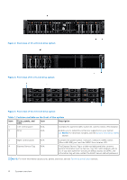
Table 5. Rear view of the system (continued) Item Ports, panels, or slots Icon Description NOTE: If the server stops responding during POST, press and hold the System ID button for more than five seconds to enter the BIOS progress mode NOTE: To reset the iDRAC (if not disabled on the iDRAC setup page by pressing F2 during system boot), press and hold the System ID button for more than 15 seconds. 12 OCP NIC card (optional) N/A 13 NIC ports (optional) 14 Power supply unit (PSU1) The OCP NIC card supports OCP 3.0. The NIC ports are integrated on the OCP card which is connected to the system board. The NIC ports that are integrated on the LOM card provide network connectivity which is connected to the system board. PSU1 is the primary PSU of the system. Figure 9. Rear view of the system with optional liquid cooling Table 6. Rear view of the system with optional liquid cooling Item Ports, panels, or slots Icon Description 1 PCIe expansion card riser 1 N/A (slot 1 and slot 2) The expansion card riser enables you to connect PCI Express expansion cards. For more information , see the Expansion card installation guidelines section. 2 BOSS blank N/A Insert BOSS blank when BOSS module is not used. 3 PCIe expansion card riser 2 N/A (slot 3 and slot 6) The expansion card riser enables you to connect PCI Express expansion cards. For more information , see the Expansion card installation guidelines section. 4 PCIe expansion card riser 3 N/A (slot 5) The expansion card riser enables you to connect PCI Express expansion cards. For more information , see the Expansion card installation guidelines section. 5 Coolant tubes N/A Cold coolant flows into the system from one tube and hot coolant leaves the system from another tube. 6 PCIe expansion card riser 4 N/A (slot 7) The expansion card riser enables you to connect PCI Express expansion cards. For more information , see the Expansion card installation guidelines section. 7 Power supply unit (PSU2) PSU2 is the secondary PSU of the system. 8 USB 2.0 port 9 USB 3.0 port The USB port is 4-pin, 2.0-compliant. This port enables you to connect USB devices to the system. The USB port is 9-pin and 3.0-compliant. This port enables you to connect USB devices to the system. 14 System overview
-
 1
1 -
2
-
3
-
4
-
5
-
6
-
7
-
8
-
 9
9 -
 10
10 -
 11
11 -
 12
12 -
 13
13 -
 14
14 -
 15
15 -
 16
16 -
 17
17 -
 18
18 -
 19
19 -
20
-
21
-
22
-
23
-
24
-
25
-
26
-
27
-
28
-
29
-
30
-
31
-
32
-
33
-
34
-
35
-
36
-
37
-
38
-
39
-
40
-
41
-
42
-
43
-
44
-
45
-
46
-
47
-
48
-
49
-
50
-
51
-
52
-
53
-
54
-
55
-
56
-
57
-
58
-
59
-
60
-
61
-
62
-
63
-
64
-
65
-
66
-
67
-
68
-
69
-
70
-
71
-
72
-
73
-
74
-
75
-
76
-
77
-
78
-
79
-
80
-
81
-
82
-
83
-
84
-
85
-
86
-
87
-
88
-
89
-
90
-
91
-
92
-
93
-
94
-
95
-
96
-
97
-
98
-
99
-
100
-
101
-
102
-
103
-
104
-
105
-
106
-
107
-
108
-
109
-
110
-
111
-
112
-
113
-
114
-
115
-
116
-
117
-
118
-
119
-
120
-
121
-
122
-
123
-
124
-
125
-
126
-
127
-
128
-
129
-
130
-
131
-
132
-
133
-
134
-
135
-
136
-
137
-
138
-
139
-
140
-
141
-
142
-
143
-
144
-
145
-
146
-
147
-
148
-
149
-
150
-
151
-
152
-
153
-
154
-
155
-
156
-
157
-
158
-
159
-
160
-
161
-
162
-
163
-
164
-
165
-
166
-
167
-
168
-
169
-
170
-
171
-
172
-
173
-
174
-
175
-
176
-
177
-
178
-
179
-
180
-
181
-
182
-
183
-
184
-
185
-
186
-
187
-
188
-
189
-
190
-
191
-
192
-
193
-
194
-
195
-
196
-
197
-
198
-
199
-
200
-
201
-
202
-
203
-
204
-
205
-
206
-
207
-
208
-
209
-
210
-
211
-
212
-
213
-
214
-
215
-
216
-
217
-
218
-
219
-
220
-
221
-
222
-
223
-
224
-
225
-
226
-
227
-
228
-
229
-
230
-
231
-
232
-
233
-
234
-
235
-
236
-
237
-
238
-
239
-
240
-
241
-
242
-
243
-
244
-
245
-
246
-
247
-
248
-
249
-
250
-
251
-
252
-
253
-
254
-
255
-
256
-
257
-
258
-
259
-
260
-
261
-
262
-
263
-
264
-
265
-
266
-
267
-
268
-
269
-
270
-
271
-
272
-
273
-
274
-
275
-
276
-
277
-
278
-
279
-
280
-
281
-
282
-
283
-
284
-
285
-
286
-
287
-
288
-
289
-
290
-
291
-
292
-
293
-
294
-
295
-
296
-
297
-
298
-
299
-
300
-
301
-
302
-
303
-
304
-
305
-
306
-
307
-
308
-
309
-
310
-
311
-
312
-
313
-
314
-
315
-
316
-
317
-
318
-
319
-
320
-
321
-
322
-
323
-
324
-
325
-
326
-
327
-
328
-
329
-
330
-
331
-
332
 |
 |
