Dell PowerVault 130T DLT Service Manual - Page 40
Required Tools, Customer Replaceable Units, Field Replaceable Units
 |
View all Dell PowerVault 130T DLT manuals
Add to My Manuals
Save this manual to your list of manuals |
Page 40 highlights
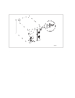
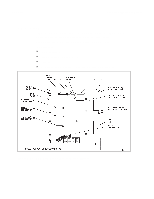
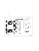
Required Tools PowerVault 130T Service Manual Required Tools The following tools are required for some removal/replace procedures and must be provided by the customer: Flashlight Torx screwdriver Wire clipper Customer Replaceable Units Customer Replaceable Units (CRUs) are designed to be removed/replaced by an individual with minimal technical experience. Follow all precautions and instructions. Table 3-1. CRU Locations and Functions Units Locations Functions Page #s DLT drive tray Left rear of the assembly library Holds tape drive and its power supply 3-13 Field Replaceable Units Field Replaceable Units (FRUs) are to be removed/replaced only by technically trained service personnel. Table 3-2. FRU Locations and Functions Units Locations Functions Page #s CYC card Part of the Microprocessor that monitors electronics module and controls all functions of 3-6 (EM) the 130T library. CYO card Front of the Displays library and drive (operator panel library, above the statuses. Used for configuring assembly) CAP. the system, running 3-8 diagnostics, and examining errors. DLT Drive Tray Left rear of the Assembly library Holds drive assembly for read/write operations 3-13 Electronics module Right rear of the Houses the power supply, library CYC card, fan assemblies 3-19 Hand/camera assembly Attaches to the bearing block on the Z column Mounts and dismounts cartridge tapes from storage cells and tape drives. 3-25 3-4 4473D
-
 1
1 -
2
-
3
-
4
-
5
-
6
-
7
-
8
-
9
-
10
-
11
-
12
-
13
-
14
-
15
-
16
-
17
-
18
-
19
-
20
-
21
-
22
-
23
-
24
-
25
-
26
-
27
-
28
-
29
-
30
-
31
-
32
-
33
-
34
-
 35
35 -
 36
36 -
 37
37 -
 38
38 -
 39
39 -
 40
40 -
 41
41 -
 42
42 -
 43
43 -
 44
44 -
 45
45 -
46
-
47
-
48
-
49
-
50
-
51
-
52
-
53
-
54
-
55
-
56
-
57
-
58
-
59
-
60
-
61
-
62
-
63
-
64
-
65
-
66
-
67
-
68
-
69
-
70
-
71
-
72
-
73
-
74
-
75
-
76
-
77
-
78
-
79
-
80
-
81
-
82
-
83
-
84
-
85
-
86
-
87
-
88
-
89
-
90
-
91
-
92
-
93
-
94
-
95
-
96
 |
 |
