Dell PowerVault 130T DLT Service Manual - Page 59
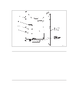
See Detail A of Connector J15D
 |
View all Dell PowerVault 130T DLT manuals
Add to My Manuals
Save this manual to your list of manuals |
Page 59 highlights
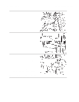
PowerVault 130T Service Manual Electronics Module Replacement WARNING: Do not apply power to the electronics module assembly when it is not installed in the PowerVault 130T. (Refer to S04 in the Safety Booklet.) 1. Verify that the jumper position and cable connections for the single-ended or differential alternative at connector J12 on the CYC card match those of the CYC card you are replacing. The jumper connects the middle row of pins on J12 to one of the following rows: (See Detail A of Figure 3-8.) Differential: Upper row (toward the top of the CYC card), to the left of the word "DIFF" silkscreened on the CYC card. Single-ended: Lower row (below DIFF), to the left of the word "SING" silkscreened on the CYC card. 2. Verify that the cables connect the two SCSI connectors on the back panel of the electronics module to one of the following connectors on the CYC card: Differential: Connector J15D Single-ended: Connector J15S 3. Set the jumper position for TERMPWR at connector J14 to match the position on the card being replaced. The jumper connects the middle pin of J14 with the one of the following pins: (See Detail A of Figure 3-8.) TERMPWR off: Left pin (toward the left of the CYC card), near the word "OFF" silkscreened on the CYC card. TERMPWR on: Right pin (toward the right of the CYC card), near the word "ON" silkscreened on the CYC card. NOTE: "Bottom", "top", "left", and "right" in Step 3 refers to directions on the CYC card on the component side with the silkscreened words appearing normally. 4. Slide the electronics module into the library. Use care not to snag loose cables. 5. Connect the cables to the J31, J25, J17, J37 and J39 connectors on the CYC card. 6. Connect the drive power plugs to the electronics module. 7. Install the four screws to the top and bottom of the electronics module using a Torx driver with a T-15 bit. Refer to the illustration in Step 7 on page 3-20. 8. Connect the customer's SCSI cable connectors to the electronics module. Refer to the illustration in Step 5 on page 3-20. 9. Close the hinged access door. 10. Tighten the three thumbscrews on the hinged access door. 11. Connect the AC power cable to the electronics module. 4473D 3-23
-
 1
1 -
2
-
3
-
4
-
5
-
6
-
7
-
8
-
9
-
10
-
11
-
12
-
13
-
14
-
15
-
16
-
17
-
18
-
19
-
20
-
21
-
22
-
23
-
24
-
25
-
26
-
27
-
28
-
29
-
30
-
31
-
32
-
33
-
34
-
35
-
36
-
37
-
38
-
39
-
40
-
41
-
42
-
43
-
44
-
45
-
46
-
47
-
48
-
49
-
50
-
51
-
52
-
53
-
 54
54 -
 55
55 -
 56
56 -
 57
57 -
 58
58 -
 59
59 -
 60
60 -
 61
61 -
 62
62 -
 63
63 -
 64
64 -
65
-
66
-
67
-
68
-
69
-
70
-
71
-
72
-
73
-
74
-
75
-
76
-
77
-
78
-
79
-
80
-
81
-
82
-
83
-
84
-
85
-
86
-
87
-
88
-
89
-
90
-
91
-
92
-
93
-
94
-
95
-
96
 |
 |
