Dell PowerVault TL4000 SCSI Reference Guide - Page 33
Error, Event, Structure
 |
View all Dell PowerVault TL4000 manuals
Add to My Manuals
Save this manual to your list of manuals |
Page 33 highlights
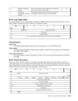
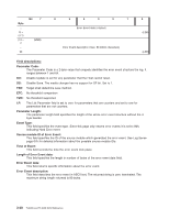
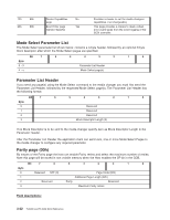
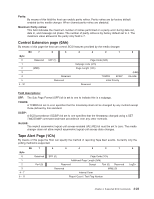
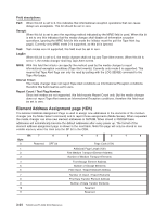
8 Number of Warning This 4 byte unsigned counter specifies the number of 0 0 Entries Warning entries in the trace buffer. 9 Number of This 4 byte unsigned counter specifies the number of 0 0 Configuration Change Configuration Change entries in the trace buffer. Entries Error Log Page (33h) This page consists out of a Page Header followed by a FIFO containing the last 64 error events. This log data is helpful to determine the error history of the media changer. Bit 7 6 5 4 3 2 1 0 Byte 0 Reserved Page Code (33h) 1 Reserved 2 - 3 Page Length 4 6211 Up to maximum 64 Hardware Error event structures (64*97 bytes) Field descriptions: Page Code: The Page Code echoes the page code that was specific in the LOG SENSE CDB. Page Length: The Page Length specifies the total number of bytes contained in this log page, not including the four bytes of the header. Error event structures: This field contains a dump of the last error events. Up to 64 error event structures are returned in this page. Error Event Structure Every error event structure consists of two parts: a header and its data. The event header contains info about event type, source, timestamp, and data length. The event data returns specific info about the error event. Appended to the event data is a error event description of maximum 80 ASCII characters with clear written text about the error event. See description in next structure: Byte 0 1 2 3 4 5 - 6 7 - 10 11 12 13 Bit 7 (MSB) DU(0) (MSB) 6 5 4 3 2 1 0 DS(1) Parameter Code TSD(0) ETC(0) TMC(0) Reserved Parameter Length (5Dh) Event type (80h) Source module ID of Error Event Timestamp of Error Event Reserved Length of Error Event data (n) Reserved (LSB) LP(0) Chapter 3. Supported SCSI Commands 3-19
-
 1
1 -
2
-
3
-
4
-
5
-
6
-
7
-
8
-
9
-
10
-
11
-
12
-
13
-
14
-
15
-
16
-
17
-
18
-
19
-
20
-
21
-
22
-
23
-
24
-
25
-
26
-
27
-
 28
28 -
 29
29 -
 30
30 -
 31
31 -
 32
32 -
 33
33 -
 34
34 -
 35
35 -
 36
36 -
 37
37 -
 38
38 -
39
-
40
-
41
-
42
-
43
-
44
-
45
-
46
-
47
-
48
-
49
-
50
-
51
-
52
-
53
-
54
-
55
-
56
-
57
-
58
-
59
-
60
-
61
-
62
-
63
-
64
-
65
-
66
-
67
-
68
-
69
-
70
-
71
-
72
-
73
-
74
-
75
-
76
-
77
-
78
-
79
-
80
-
81
-
82
-
83
-
84
-
85
-
86
-
87
-
88
-
89
-
90
-
91
-
92
-
93
-
94
-
95
-
96
-
97
-
98
-
99
-
100
-
101
-
102
-
103
-
104
-
105
-
106
-
107
-
108
-
109
-
110
-
111
-
112
-
113
-
114
-
115
-
116
 |
 |
