Dell PowerVault TL4000 SCSI Reference Guide - Page 38
Element, Address, Assignment
 |
View all Dell PowerVault TL4000 manuals
Add to My Manuals
Save this manual to your list of manuals |
Page 38 highlights
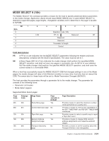
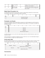
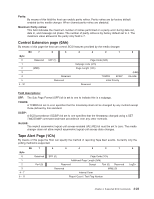
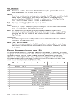
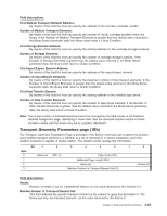
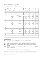
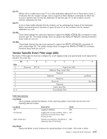
Field descriptions: Perf: When this bit is set to 0, this indicates that informational exception operations that can cause delays are acceptable. This bit should be set to zero. Dexcpt: When this bit is set to zero the reporting method indicated by the MRIE field is used. When this bit is set to one this indicates that the media changer shall disable all information exception operations, ignoring the MRIE field (In this mode the initiator must the poll the Tape Alert log page). Currently only MRIE mode 0 is supported, so this bit is ignored. Test: Test modes are not supported, this field must be set to zero. LogErr: When this bit is set to 0, the media changer shall not log any Tape Alert events. When this bit is set to 1, the media changer shall log Tape Alert events. MRIE: With this field the initiator can specify the method used by the media changer to report informational exception conditions (Tape Alert events). Currently only mode 0 is supported. This means that Tape Alert flags can only be read by polling with the LOG SENSE command to the Tape Alert page. Interval Timer: The media changer does not report Tape Alert conditions as Informational Exception conditions, therefore this field must be set to zero. Report Count / Test Flag Number: Since test modes are not supported, this field reports Report Count only. But the media changer does not report Tape Alert events as Informational Exception conditions, therefore this field must be set to zero. Element Address Assignment page (1Dh) The Element Address Assignment Page is used to assign new addresses to the elements of the medium changer (via the Mode Select command) and to report those assignments (Mode Sense). When requested the media changer can store new element addresses in NVRAM. When stored in NVRAM these addresses will automatically become the default addresses after every power up. The format of the element address assignment page is shown in the next table. Note this page will only be stored in non volatile memory when the Host sets the SP bit in the CDB. Bit 7 6 5 4 3 2 1 0 Byte 0 Reserved SPF (0) Page Code (1Dh) 1 Additional Page Length (12h) 2 First Medium Transport Element Address 3 Number of Medium Transport Elements 4 First Storage Element Address 5 Number of Storage Elements 6 First Import / Export Element Address 7 Number of Import / Export Elements 8 First Data Transfer Element Address 9 Number of Data Transfer Elements 10 Reserved 11 Reserved 3-24 TL2000 and TL4000 SCSI Reference
-
 1
1 -
2
-
3
-
4
-
5
-
6
-
7
-
8
-
9
-
10
-
11
-
12
-
13
-
14
-
15
-
16
-
17
-
18
-
19
-
20
-
21
-
22
-
23
-
24
-
25
-
26
-
27
-
28
-
29
-
30
-
31
-
32
-
 33
33 -
 34
34 -
 35
35 -
 36
36 -
 37
37 -
 38
38 -
 39
39 -
 40
40 -
 41
41 -
 42
42 -
 43
43 -
44
-
45
-
46
-
47
-
48
-
49
-
50
-
51
-
52
-
53
-
54
-
55
-
56
-
57
-
58
-
59
-
60
-
61
-
62
-
63
-
64
-
65
-
66
-
67
-
68
-
69
-
70
-
71
-
72
-
73
-
74
-
75
-
76
-
77
-
78
-
79
-
80
-
81
-
82
-
83
-
84
-
85
-
86
-
87
-
88
-
89
-
90
-
91
-
92
-
93
-
94
-
95
-
96
-
97
-
98
-
99
-
100
-
101
-
102
-
103
-
104
-
105
-
106
-
107
-
108
-
109
-
110
-
111
-
112
-
113
-
114
-
115
-
116
 |
 |