Dell Precision 410 Dell Precision WorkStation 410 Desktop Systems User's Guide - Page 89
Diagnostics and, Troubleshooting Guide
 |
View all Dell Precision 410 manuals
Add to My Manuals
Save this manual to your list of manuals |
Page 89 highlights
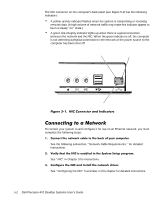
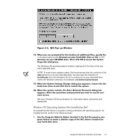
See the chapter titled "Running the Dell Diagnostics" in your Diagnostics and Troubleshooting Guide for detailed instructions. Your computer's NIC connector (an RJ45 connector located on the back panel; see Figure 5-1) is designed for attaching an unshielded twisted pair (UTP) Ethernet cable. Press one end of the UTP cable into the NIC connector until the cable snaps securely into place. Connect the other end of the cable to an RJ45 jack wall plate or to an RJ45 port on an Ethernet UTP concentrator or hub, depending on your network configuration. Observe the following cabling restrictions for 10BASE-T and 100BASE-TX networks: For 10-megabit (Mb) operation, use Category 3, 4, or 5 wiring and connectors. For 100-Mb operation, use Category 5 wiring and connectors. Voice and data lines should be in separate sheaths. The maximum cable run length (from a workstation to a concentrator) is 100 meters (m) (328 feet [(ft]). The maximum number of workstations (not counting concentrators) on a network is 1024. The maximum number of daisy-chained concentrators on one network segment is four. This section describes how to set the network frame type for an Internetwork Packet eXchange/Sequenced Packet eXchange (IPX/SPX)-compatible network protocol, If your system is connected to a network, follow these steps: Using the Network Interface Controller 5-3
-
 1
1 -
2
-
3
-
4
-
5
-
6
-
7
-
8
-
9
-
10
-
11
-
12
-
13
-
14
-
15
-
16
-
17
-
18
-
19
-
20
-
21
-
22
-
23
-
24
-
25
-
26
-
27
-
28
-
29
-
30
-
31
-
32
-
33
-
34
-
35
-
36
-
37
-
38
-
39
-
40
-
41
-
42
-
43
-
44
-
45
-
46
-
47
-
48
-
49
-
50
-
51
-
52
-
53
-
54
-
55
-
56
-
57
-
58
-
59
-
60
-
61
-
62
-
63
-
64
-
65
-
66
-
67
-
68
-
69
-
70
-
71
-
72
-
73
-
74
-
75
-
76
-
77
-
78
-
79
-
80
-
81
-
82
-
83
-
 84
84 -
 85
85 -
 86
86 -
 87
87 -
 88
88 -
 89
89 -
 90
90 -
 91
91 -
 92
92 -
 93
93 -
 94
94 -
95
-
96
-
97
-
98
-
99
-
100
-
101
-
102
-
103
-
104
-
105
-
106
-
107
-
108
-
109
-
110
-
111
-
112
-
113
-
114
-
115
-
116
-
117
-
118
-
119
-
120
-
121
-
122
-
123
-
124
-
125
-
126
-
127
-
128
-
129
-
130
-
131
-
132
-
133
-
134
-
135
-
136
-
137
-
138
-
139
-
140
-
141
-
142
-
143
-
144
-
145
-
146
-
147
-
148
-
149
-
150
-
151
-
152
-
153
-
154
-
155
-
156
-
157
-
158
-
159
-
160
-
161
-
162
-
163
-
164
-
165
-
166
-
167
-
168
-
169
-
170
-
171
-
172
-
173
-
174
-
175
-
176
-
177
-
178
-
179
-
180
-
181
-
182
-
183
-
184
-
185
-
186
-
187
-
188
-
189
-
190
-
191
-
192
-
193
-
194
-
195
-
196
-
197
-
198
-
199
-
200
-
201
-
202
-
203
-
204
-
205
-
206
-
207
-
208
-
209
-
210
-
211
-
212
-
213
-
214
-
215
-
216
-
217
-
218
-
219
-
220
-
221
-
222
-
223
-
224
-
225
-
226
-
227
-
228
-
229
-
230
-
231
-
232
-
233
-
234
-
235
-
236
-
237
-
238
 |
 |
