Dell Z9100 EMC Networking with Isilon Front-End Deployment and Best Practices - Page 13
Scaling, 320GbE = 5120GbE
 |
View all Dell Z9100 manuals
Add to My Manuals
Save this manual to your list of manuals |
Page 13 highlights
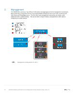
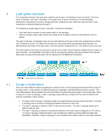
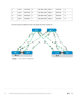
10GbE 38 10GbE 38 10GbE 38 380GbE 380GbE 380GbE 2 100GbE 80GbE 380/200 3 100GbE 120GbE 380/300 4 100GbE 160GbE 380/400 1.900 : 1 1.267 : 1 0.950 : 1 4.3 Scaling An example of scaling this solution in a two-tier leaf-spine is a configuration of up to 16 racks. The Dell/EMC Z9100-ON has thirty-two 40/100GbE interfaces that would support 16 leaf pairs using VLT. This provides one rack that contains WAN-edge connectivity and 15 racks for servers and storage nodes. Each rack of the compute/storage rack holding a combination of up to 19 PowerEdge R730's or Isilon X210's. This particular example, each R730 has four 10GbE uplinks, and each Isilon node has four 10GbE uplinks with 19 servers/nodes per rack. Additionally, the example architecture has four spine switches to minimize oversubscription. Connections for 16 racks with 4 spine switches Server/Storage Server Leaf connections to spine interfaces connections to switches per rack leaf switches Connections 4 19 x 4 = 76 4 per leaf switch, 2 leaf switches per rack = 8 links Speed of 10 GbE 10 GbE 40 GbE Ports Total 4 x 10 = 76 x10 = 8 * 40GbE per rack = theoretical 40GbE 760GbE 320GbE available bandwidth Total connections for leaf switches to four spine switches 16 racks * 8 = 128 40 GbE 16 * 320GbE = 5120GbE This example provides for an oversubscription rate of 2.375:1 using 40GbE spine connectivity. Scaling beyond 16 racks would require a three-tier leaf-spine network. The proof-of-concept scaling that Figure 11 shows allows four 16-rack pods connected using an additional spine layer to scale in excess of 1,000 nodes with the same oversubscription ratio. This scenario requires reducing the number of racks available per pod to accommodate the uplinks required to connect to the super spine layer. It is important to understand the port-density of switches used and their feature sets' impact on the number of available ports. This directly influences the number of switches necessary for proper scaling. 13 Dell EMC Networking with Isilon Front-End Deployment and Best Practices Guide | version 1.0
-
 1
1 -
2
-
3
-
4
-
5
-
6
-
7
-
 8
8 -
 9
9 -
 10
10 -
 11
11 -
 12
12 -
 13
13 -
 14
14 -
 15
15 -
 16
16 -
 17
17 -
 18
18 -
19
-
20
-
21
-
22
-
23
-
24
-
25
-
26
-
27
-
28
-
29
-
30
-
31
-
32
-
33
-
34
-
35
-
36
-
37
-
38
-
39
-
40
-
41
-
42
-
43
-
44
-
45
-
46
-
47
-
48
-
49
-
50
-
51
-
52
-
53
-
54
-
55
-
56
-
57
-
58
-
59
-
60
-
61
-
62
-
63
-
64
-
65
-
66
-
67
-
68
-
69
-
70
-
71
-
72
-
73
-
74
-
75
-
76
-
77
-
78
 |
 |
