Dell Z9100 EMC Networking with Isilon Front-End Deployment and Best Practices - Page 17
Point-to-point interfaces
 |
View all Dell Z9100 manuals
Add to My Manuals
Save this manual to your list of manuals |
Page 17 highlights
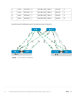
10.0.1.1/32 10.0.1.2/32 5.3 10.0.2.1/32 10.0.2.2/32 Rack 1 10.0.2.3/32 10.0.2.4/32 Rack 2 Loopback addressing All loopback addresses used are part of the 10.0.0.0/8 address space with each address using a 32-bit mask. In this example, the third octet represents the layer, "1" for the spine and "2" for the leaf. The fourth octet is the counter for the appropriate layer. For example, 10.0.1.1/32 is the first spine switch in the topology while 10.0.2.4/32 is the fourth leaf switch. Point-to-point interfaces Table 3 lists layer 3 connection details for each leaf and spine switch. All addresses come from the same base IP prefix, 192.168.0.0/16 with the third octet representing the spine number. For example, 192.168.1.0/31 is a two-host subnet connected to Spine 1 while 192.168.2.0/31 is connected to Spine 2. This IP scheme is easily extended as leaf and spine switches are added to the network. Link labels are provided in the table for quick reference with Figure 16. Link Label Interface and IP configuration Source Source Source switch interface IP Network Destination Destination Destination switch interface IP A Leaf 1 Eth1/1/49 .1 B Leaf 1 Eth1/1/50 .1 C Leaf 2 Eth1/1/49 .3 D Leaf 2 Eth1/1/50 .3 192.168.1.0/31 Spine 1 192.168.2.0/31 Spine 2 192.168.1.2/31 Spine 1 192.168.2.2/31 Spine 2 Eth1/1/1 .0 Eth1/1/1 .0 Eth1/1/2 .2 Eth1/1/2 .2 17 Dell EMC Networking with Isilon Front-End Deployment and Best Practices Guide | version 1.0
-
 1
1 -
2
-
3
-
4
-
5
-
6
-
7
-
8
-
9
-
10
-
11
-
 12
12 -
 13
13 -
 14
14 -
 15
15 -
 16
16 -
 17
17 -
 18
18 -
 19
19 -
 20
20 -
 21
21 -
 22
22 -
23
-
24
-
25
-
26
-
27
-
28
-
29
-
30
-
31
-
32
-
33
-
34
-
35
-
36
-
37
-
38
-
39
-
40
-
41
-
42
-
43
-
44
-
45
-
46
-
47
-
48
-
49
-
50
-
51
-
52
-
53
-
54
-
55
-
56
-
57
-
58
-
59
-
60
-
61
-
62
-
63
-
64
-
65
-
66
-
67
-
68
-
69
-
70
-
71
-
72
-
73
-
74
-
75
-
76
-
77
-
78
 |
 |
