Epson BrightLink 436Wi Installation Guide - Page 32
Attach the cable cover to the projector
 |
View all Epson BrightLink 436Wi manuals
Add to My Manuals
Save this manual to your list of manuals |
Page 32 highlights
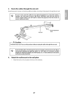
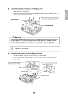
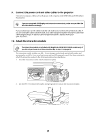
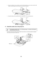
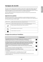
3. Remove the USB port cover, and then connect the USB cable. Make sure the other end of the USB cable is routed through the arm unit and connected to the computer. 4. Attach the USB port cover, and then secure it using the M3 × 8 mm cross-head screw. 11. Attach the cable cover to the projector The interactive module shown in the following images is included with BrightLink 425Wi/430i/435Wi models only. Take up the cable slack, and then attach the cable cover and use a cross-head screwdriver to tighten the screws (2) and secure the cable cover. Cable cover 32
-
 1
1 -
2
-
3
-
4
-
5
-
6
-
7
-
8
-
9
-
10
-
11
-
12
-
13
-
14
-
15
-
16
-
17
-
18
-
19
-
20
-
21
-
22
-
23
-
24
-
25
-
26
-
 27
27 -
 28
28 -
 29
29 -
 30
30 -
 31
31 -
 32
32 -
 33
33 -
 34
34 -
 35
35 -
 36
36 -
 37
37 -
38
-
39
-
40
-
41
-
42
-
43
-
44
-
45
-
46
-
47
-
48
-
49
-
50
-
51
-
52
-
53
-
54
-
55
-
56
-
57
-
58
-
59
-
60
-
61
-
62
-
63
-
64
-
65
-
66
-
67
-
68
-
69
-
70
-
71
-
72
 |
 |
32
3.
Remove the USB port cover, and then connect the USB cable. Make sure the other end of the USB
cable is routed through the arm unit and connected to the computer.
4.
Attach the USB port cover, and then secure it using the M3 × 8 mm cross-head screw.
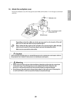
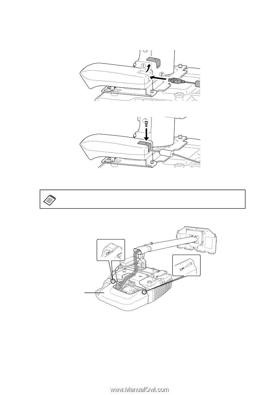
11.
Attach the cable cover to the projector
Take up the cable slack, and then attach the cable cover and use a cross-head screwdriver to tighten
the screws (2) and secure the cable cover.
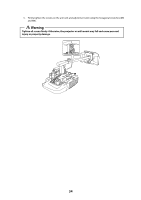
The interactive module shown in the following images is included with BrightLink
425Wi/430i/435Wi models only.
Cable cover