Foxconn Destroyer English Manual. - Page 22
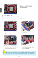
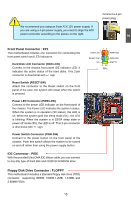
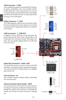
Front Panel Connector : FP1, IDE Connector : PIDE
 |
View all Foxconn Destroyer manuals
Add to My Manuals
Save this manual to your list of manuals |
Page 22 highlights
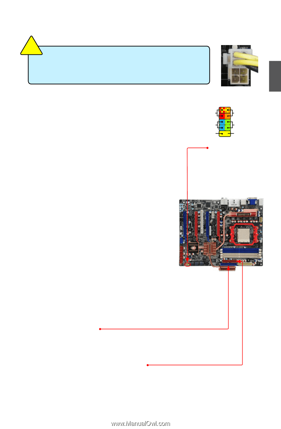
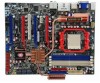
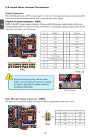
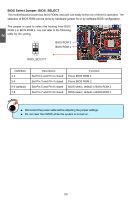
CAUTION ! We recommend you using an 8-pin ATX 12V power supply. If you are using a 4-pin power supply, you need to align the ATX power connector according to the picture on the right. Connect a 4-pin power plug 2 Front Panel Connector : FP1 This motherboard includes one connector for connecting the front panel switch and LED Indicators. Hard Disk LED Connector (HDD-LED) Connect to the chassis front panel IDE indicator LED. It indicates the active status of the hard disks. This 2-pin connector is directional with +/- sign. Reset Switch (RESET-SW) Attach the connector to the Reset switch on the front panel of the case; the system will restart when the switch is pressed. Power LED Connector (PWR-LED) Connect to the power LED indicator on the front panel of the chassis. The Power LED indicates the system's status. When the system is in operation (S0 status), the LED is on. When the system gets into sleep mode (S1) , the LED is blinking; When the system is in S3/S4 sleep state or power off mode (S5), the LED is off. This 2-pin connector is directional with +/- sign. Power Switch Connector (PWR-SW) Connect to the power button on the front panel of the chassis. Push this switch allows the system to be turned on and off rather than using the power supply button. IDE Connector : PIDE With the provided Ultra DMA IDE ribbon cable, you can connect to any IDE type of hard disk and CD/DVD ROM/RW drive. Floppy Disk Drive Connector : FLOPPY This motherboard includes a standard floppy disk drive (FDD) connector, supporting 360KB, 720KB,1.2MB, 1.44MB, and 2.88MB FDDs. 1 + HDD-LED - 2 + PWR-LED - RESET-SW PWR-SW NC EMPTY 9 10 FP1 15
-
 1
1 -
2
-
3
-
4
-
5
-
6
-
7
-
8
-
9
-
10
-
11
-
12
-
13
-
14
-
15
-
16
-
 17
17 -
 18
18 -
 19
19 -
 20
20 -
 21
21 -
 22
22 -
 23
23 -
 24
24 -
 25
25 -
 26
26 -
 27
27 -
28
-
29
-
30
-
31
-
32
-
33
-
34
-
35
-
36
-
37
-
38
-
39
-
40
-
41
-
42
-
43
-
44
-
45
-
46
-
47
-
48
-
49
-
50
-
51
-
52
-
53
-
54
-
55
-
56
-
57
-
58
-
59
-
60
-
61
-
62
-
63
-
64
-
65
-
66
-
67
-
68
-
69
-
70
-
71
-
72
-
73
-
74
-
75
-
76
-
77
-
78
-
79
-
80
-
81
-
82
-
83
-
84
-
85
-
86
-
87
-
88
-
89
-
90
-
91
-
92
-
93
-
94
-
95
-
96
-
97
-
98
-
99
-
100
-
101
-
102
-
103
-
104
-
105
-
106
-
107
-
108
-
109
-
110
-
111
-
112
-
113
 |
 |