Foxconn Destroyer English Manual. - Page 48
► SLI-Ready Memory - am2
 |
View all Foxconn Destroyer manuals
Add to My Manuals
Save this manual to your list of manuals |
Page 48 highlights
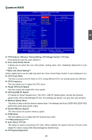
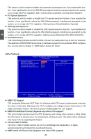
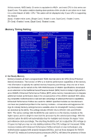
At this moment, AMD family 10 series is equivalent to AM2+, and most CPU in this series are Quad Cores. This option enables shutting down portions of the circuits in core when not in load, it is a new feature of AM2+ CPU. This option will be displayed only if your CPU is supporting this feature. [Auto] : Enable entire cores, [Single Core] : Enable 1 core, Dual Core] : Enable 2 cores, [Tri Core] : Enable 3 cores, [Quad Core] : Enable 4 cores. 3 Memory Timing Setting Phoenix - AwardBIOS CMOS Setup Utility Memory Timing Setting SLI-Ready Memory [Disabled ] Not Detect SPD Checksum Restart [Ignore] CKE Based Power Down Mode [Disabled] CKE Based Power Down [Per Channel] Memclock Tri-stating [Disabled] Memory Hole Remapping [Enabled] Auto Optimize Bottom IO [Enabled] x Bottom of [31:24] IO Space C0 Bottom of UMA DRAM [31:24] [FC] DRAM Timing Selectable By SPD x 1T/2T Memory Timing Auto x CAS# Latency (tCL) Auto x RAS to CAS Delay (tRCD) Auto x Row Precharge Time (tRP) Auto x Min RAS Active Time (tRAS) Auto x Write Recovery Time (tWR) Auto x Write to Read Delay (tWTR) Auto x RAS to RAS Delay (tRRD) Auto x Read to Precharge (tRTP) Auto Item Help Menu Level ► "CPUOC MAX" realizes the complete optimized memory settings when SLI-Ready memory is installed Optimize memory settings by allowing X % CPU overclocking CPU overclocking may require manual overvoltaging of the CPU to improve system stability Move Enter:Select +/-/PU/PD:Value F10:Save ESC:Exit F1:General Help F5:Previous Values F7:Optimized Defaults ► SLI-Ready Memory Memory modules all have a programmable ROM chip that stores the SPD (Serial Presence Detect) information. The function of SPD is to hold the performance capabilities of the memory. This information is typically the optimal memory frequency and timings. Only one set of memory information can be stored on the SPD ROM because of JEDEC specifications. Developed as an extension to the traditional Serial Presence Detect (SPD) found on today's high-performance DIMMS, Enhanced Performance Profiles (EPP) allow memory manufacturers to integrate additional module performance data in the unused portion of the JEDEC standard SPD, allowing compatible motherboards to read and take advantage of added performance capabilities. Enhanced Performance Profiles are useful for JEDEC specified modules as manufacturers can have two predefined profiles for the memory modules-conservative and aggressive timings.SLI-Ready Memory settings become available when SLI-Ready/EPP memory modules are detected by the BIOS. The settings include CPUOC 0% to CPUOC 13% and CPUOC MAX. The various settings tells the BIOS the user wants to run the memory modules at the higher speed, and it is alright to overclock the processor by the selected percentage. With the selected option the BIOS will automatically drop the multiplier and increase the Hyper Transport reference clock accordingly. The only thing the BIOS can't do is adjust the CPU voltage so if it goes too high you may run into stability problems if the CPU voltage isn't increased. While memory modules with Enhanced Performance Profiles will work on any motherboard, only motherboards equipped with properly-designed BIOSes, such as those designed for NVIDIA nForce® SLI media and communications processors (MCPs), will detect the presence of these 41
-
 1
1 -
2
-
3
-
4
-
5
-
6
-
7
-
8
-
9
-
10
-
11
-
12
-
13
-
14
-
15
-
16
-
17
-
18
-
19
-
20
-
21
-
22
-
23
-
24
-
25
-
26
-
27
-
28
-
29
-
30
-
31
-
32
-
33
-
34
-
35
-
36
-
37
-
38
-
39
-
40
-
41
-
42
-
 43
43 -
 44
44 -
 45
45 -
 46
46 -
 47
47 -
 48
48 -
 49
49 -
 50
50 -
 51
51 -
 52
52 -
 53
53 -
54
-
55
-
56
-
57
-
58
-
59
-
60
-
61
-
62
-
63
-
64
-
65
-
66
-
67
-
68
-
69
-
70
-
71
-
72
-
73
-
74
-
75
-
76
-
77
-
78
-
79
-
80
-
81
-
82
-
83
-
84
-
85
-
86
-
87
-
88
-
89
-
90
-
91
-
92
-
93
-
94
-
95
-
96
-
97
-
98
-
99
-
100
-
101
-
102
-
103
-
104
-
105
-
106
-
107
-
108
-
109
-
110
-
111
-
112
-
113
 |
 |