Foxconn Destroyer English Manual. - Page 23
Chassis Intrusion Alarm Header : INTR
 |
View all Foxconn Destroyer manuals
Add to My Manuals
Save this manual to your list of manuals |
Page 23 highlights
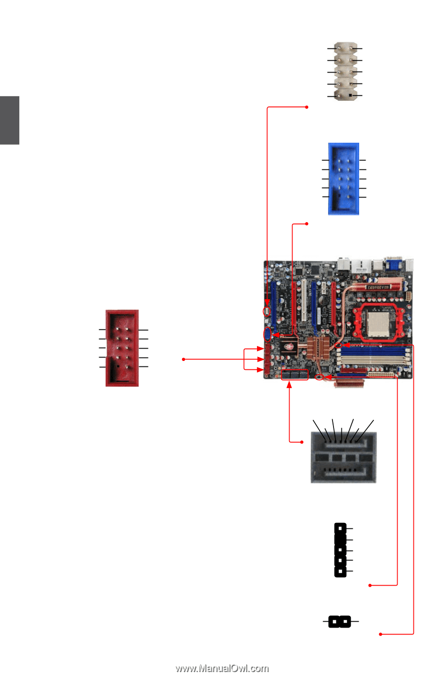
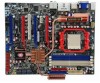
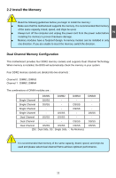
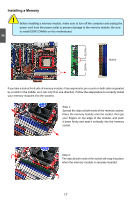
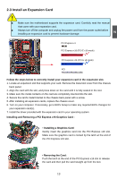
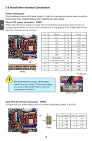
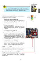
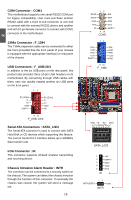
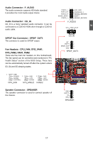
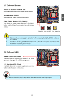
2 COM Connector : COM1 This motherboard supports one serial RS232 COM port for legacy compatibility. User must purchase another RS232 cable with a 9-pin D-sub connector at one end to connect with the external RS232 device and another end with 10-pin female connector to connect with COM1 connector in the motherboard. 1394a Connector : F_1394 The 1394a expansion cable can be connected to either the front (provided that the front panel of your chassis is equipped with the appropriate interface) or real panel of the chassis. USB Connectors : F_USB1/2/3 In addition to the six USB ports on the rear panel, this product also provides three 10-pin USB headers on its motherboard. By connecting through USB cables with them, user can quickly expand another six USB ports on the front panel. 12 5V_DUAL DD+ GND EMPTY 5V_DUAL DD+ GND NC 9 10 F_USB 1/2/3 Serial ATA Connectors : SATA_1/2/3 The Serial ATA connector is used to connect with SATA Hard Disk or CD devices which supporting this feature. The current Serial ATA II interface allows up to 300MB/s data transfer rate. IrDA Connector : IR This connector supports infrared wireless transmitting and receiving device. Chassis Intrusion Alarm Header : INTR The connector can be connected to a security switch on the chassis. The system can detect the chassis intrusion through the function of this connector. If eventually the chassis was closed, the system will send a message out. 16 12 RLSD SIN SOUT DTR GND DSR RTS CTS RI EMPTY 9 10 COM1 12 TPA+ GND TPB+ +12V EMPTY TPAGND TPB+12V GND 9 10 F_1394 GND TX- RX- GND 1 TX+ GND RX+ SATA_1/2/3 1 2 3 4 5 IR +5V EMPTY IRRX GND IRTX INTRUDERJ 12 INTR GND
-
 1
1 -
2
-
3
-
4
-
5
-
6
-
7
-
8
-
9
-
10
-
11
-
12
-
13
-
14
-
15
-
16
-
17
-
 18
18 -
 19
19 -
 20
20 -
 21
21 -
 22
22 -
 23
23 -
 24
24 -
 25
25 -
 26
26 -
 27
27 -
 28
28 -
29
-
30
-
31
-
32
-
33
-
34
-
35
-
36
-
37
-
38
-
39
-
40
-
41
-
42
-
43
-
44
-
45
-
46
-
47
-
48
-
49
-
50
-
51
-
52
-
53
-
54
-
55
-
56
-
57
-
58
-
59
-
60
-
61
-
62
-
63
-
64
-
65
-
66
-
67
-
68
-
69
-
70
-
71
-
72
-
73
-
74
-
75
-
76
-
77
-
78
-
79
-
80
-
81
-
82
-
83
-
84
-
85
-
86
-
87
-
88
-
89
-
90
-
91
-
92
-
93
-
94
-
95
-
96
-
97
-
98
-
99
-
100
-
101
-
102
-
103
-
104
-
105
-
106
-
107
-
108
-
109
-
110
-
111
-
112
-
113
 |
 |