HP 6125XLG R2306-HP 6125XLG Blade Switch MCE Configuration Guide - Page 21
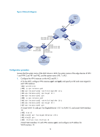
so that the MCE can learn the routes of VPN 2 and add them to the routing table of the VPN
 |
View all HP 6125XLG manuals
Add to My Manuals
Save this manual to your list of manuals |
Page 21 highlights
127.0.0.0/32 Direct 0 0 127.0.0.1 InLoop0 127.0.0.1/32 Direct 0 0 127.0.0.1 InLoop0 127.255.255.255/32 Direct 0 0 127.0.0.1 InLoop0 192.168.0.0/24 Static 60 0 10.214.10.2 Vlan10 224.0.0.0/4 Direct 0 0 0.0.0.0 NULL0 224.0.0.0/24 Direct 0 0 0.0.0.0 NULL0 255.255.255.255/32 Direct 0 0 127.0.0.1 InLoop0 The output shows that the MCE has a static route for VPN instance vpn1. # Run OSPF in VPN 2. Create OSPF process 2 and bind it with VPN instance vpn2 on the MCE, so that the MCE can learn the routes of VPN 2 and add them to the routing table of the VPN instance vpn2. [MCE] ospf 2 vpn-instance vpn2 # Advertise subnet 10.214.20.0/24. [MCE-ospf-2] area 0 [MCE-ospf-2-area-0.0.0.0] network 10.214.20.0 0.0.0.255 [MCE-ospf-2-area-0.0.0.0] quit [MCE-ospf-2] quit # On VR 2, assign IP address 10.214.20.2/24 to the interface connected to MCE and 192.168.10.1/24 to the interface connected to VPN 2. (Details not shown) # Configure OSPF process 2, and advertise subnets 192.168.10.0/24 and 10.214.20.0/24. system-view [VR2] ospf 2 [VR2-ospf-2] area 0 [VR2-ospf-2-area-0.0.0.0] network 192.168.10.0 0.0.0.255 [VR2-ospf-2-area-0.0.0.0] network 10.214.20.0 0.0.0.255 [VR2-ospf-2-area-0.0.0.0] quit [VR2-ospf-2] quit # On the MCE, display the routing information for VPN instance vpn2. [MCE] display ip routing-table vpn-instance vpn2 Destinations : 13 Routes : 13 Destination/Mask 0.0.0.0/32 10.214.20.0/24 10.214.20.0/32 10.214.20.3/32 10.214.20.255/32 127.0.0.0/8 127.0.0.0/32 127.0.0.1/32 127.255.255.255/32 192.168.10.0/24 224.0.0.0/4 224.0.0.0/24 255.255.255.255/32 Proto Pre Direct 0 Direct 0 Direct 0 Direct 0 Direct 0 Direct 0 Direct 0 Direct 0 Direct 0 OSPF 10 Direct 0 Direct 0 Direct 0 Cost 0 0 0 0 0 0 0 0 0 2 0 0 0 NextHop 127.0.0.1 10.214.20.3 10.214.20.3 127.0.0.1 10.214.20.3 127.0.0.1 127.0.0.1 127.0.0.1 127.0.0.1 10.214.20.2 0.0.0.0 0.0.0.0 127.0.0.1 Interface InLoop0 Vlan20 Vlan20 InLoop0 Vlan20 InLoop0 InLoop0 InLoop0 InLoop0 Vlan20 NULL0 NULL0 InLoop0 18
-
 1
1 -
2
-
3
-
4
-
5
-
6
-
7
-
8
-
9
-
10
-
11
-
12
-
13
-
14
-
15
-
 16
16 -
 17
17 -
 18
18 -
 19
19 -
 20
20 -
 21
21 -
 22
22 -
 23
23 -
 24
24 -
 25
25 -
 26
26 -
27
-
28
-
29
-
30
-
31
-
32
-
33
-
34
-
35
-
36
-
37
-
38
-
39
-
40
-
41
-
42
-
43
-
44
-
45
-
46
-
47
-
48
-
49
-
50
-
51
-
52
 |
 |