HP 6125XLG R2306-HP 6125XLG Blade Switch MCE Configuration Guide - Page 39
Configuration procedure, each VPN instance.
 |
View all HP 6125XLG manuals
Add to My Manuals
Save this manual to your list of manuals |
Page 39 highlights
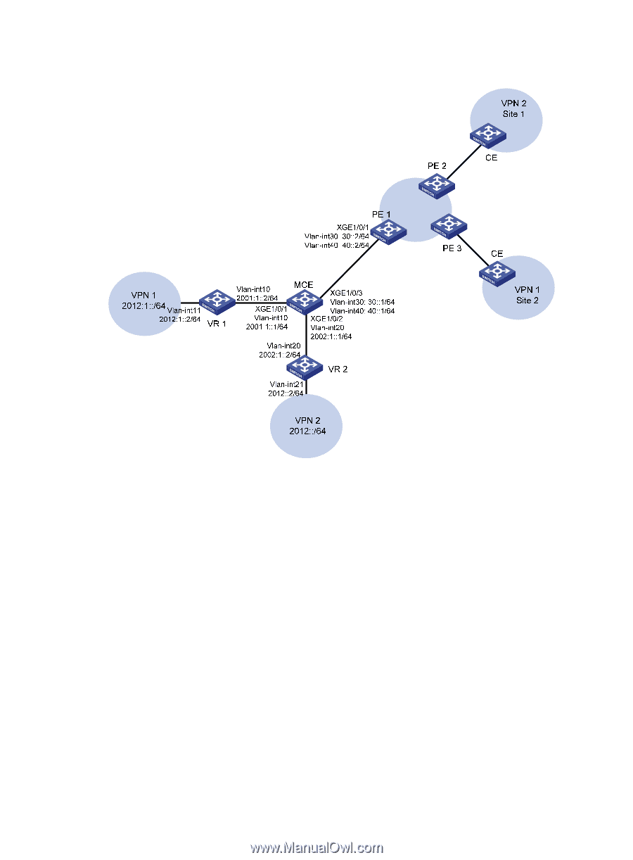
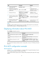
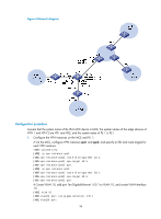
Figure 6 Network diagram Configuration procedure Assume that the system name of the IPv6 MCE device is MCE, the system names of the edge devices of VPN 1 and VPN 2 are VR1 and VR2, and the system name of PE 1 is PE1. 1. Configure the VPN instances on the MCE and PE 1: # On the MCE, configure VPN instances vpn1 and vpn2, and specify an RD and route targets for each VPN instance. system-view [MCE] ip vpn-instance vpn1 [MCE-vpn-instance-vpn1] route-distinguisher 10:1 [MCE-vpn-instance-vpn1] vpn-target 10:1 [MCE-vpn-instance-vpn1] quit [MCE] ip vpn-instance vpn2 [MCE-vpn-instance-vpn2] route-distinguisher 20:1 [MCE-vpn-instance-vpn2] vpn-target 20:1 [MCE-vpn-instance-vpn2] quit # Create VLAN 10, add port Ten-GigabitEthernet 1/0/1 to VLAN 10, and create VLAN-interface 10. [MCE] vlan 10 [MCE-vlan10] port ten-gigabitethernet 1/0/1 [MCE-vlan10] quit 36
-
 1
1 -
2
-
3
-
4
-
5
-
6
-
7
-
8
-
9
-
10
-
11
-
12
-
13
-
14
-
15
-
16
-
17
-
18
-
19
-
20
-
21
-
22
-
23
-
24
-
25
-
26
-
27
-
28
-
29
-
30
-
31
-
32
-
33
-
 34
34 -
 35
35 -
 36
36 -
 37
37 -
 38
38 -
 39
39 -
 40
40 -
 41
41 -
 42
42 -
 43
43 -
 44
44 -
45
-
46
-
47
-
48
-
49
-
50
-
51
-
52
 |
 |