HP 6125XLG R2306-HP 6125XLG Blade Switch MCE Configuration Guide - Page 7
How MCE works, Configuring VPN instances on an MCE device
 |
View all HP 6125XLG manuals
Add to My Manuals
Save this manual to your list of manuals |
Page 7 highlights
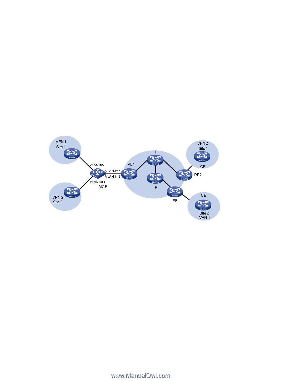
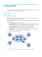
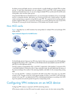
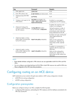
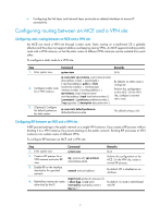
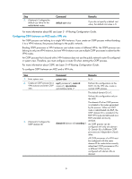
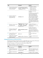
For better services and higher security, a private network is usually divided into multiple VPNs to isolate services. To meet these requirements, you can configure a CE for each VPN, which increases device expenses and maintenance costs. Or, you can configure multiple VPNs to use the same CE and the same routing table, which sacrifices data security. Using the Multi-VPN-Instance CE (MCE) function, you can remove the contradiction of low cost and high security in multi-VPN networks. MCE allows you to bind each VPN with a VLAN interface. The MCE creates and maintains a separate routing table for each VPN. This separates the forwarding paths for packets of different VPNs and, in conjunction with the PE, can correctly advertise the routes of each VPN to the peer PE, ensuring the normal transmission of VPN packets over the public network. How MCE works Figure 3 describes how an MCE maintains the routing tables for multiple VPNs and exchanges VPN routes with PEs. Figure 3 Network diagram for the MCE function On the left-side network, there are two VPN sites, both of which are connected to the MPLS backbone through the MCE device. VPN 1 and VPN 2 on the left-side network must establish a tunnel with VPN 1 and VPN 2 on the right-side network. The MCE creates a routing table for VPN 1 and VPN 2, respectively. VLAN-interface 2 is bound to VPN 1 and VLAN-interface 3 is bound to VPN 2. Upon receiving a route, the MCE determines the source of the route according to the number of the receiving interface, and adds it to the corresponding routing table. You must also bind PE 1' interfaces connected to the MCE to the VPNs in the same way. The MCE connects to PE 1 through a trunk link, which permits packets of VLAN 2 and VLAN 3 with VLAN tags carried. In this way, PE 1 can determine the VPN a received packet belongs to according to the VLAN tag of the packet and sends the packet through the corresponding tunnel. Configuring VPN instances on an MCE device Configuring VPN instances is required in all MCE networking schemes. VPN instances isolate not only VPN routes from public network routes, but also routes among VPNs. 4
-
 1
1 -
 2
2 -
 3
3 -
 4
4 -
 5
5 -
 6
6 -
 7
7 -
 8
8 -
 9
9 -
 10
10 -
 11
11 -
 12
12 -
13
-
14
-
15
-
16
-
17
-
18
-
19
-
20
-
21
-
22
-
23
-
24
-
25
-
26
-
27
-
28
-
29
-
30
-
31
-
32
-
33
-
34
-
35
-
36
-
37
-
38
-
39
-
40
-
41
-
42
-
43
-
44
-
45
-
46
-
47
-
48
-
49
-
50
-
51
-
52
 |
 |