HP 6125XLG R2306-HP 6125XLG Blade Switch MCE Configuration Guide - Page 27
into the EBGP routing table. Details not shown.
 |
View all HP 6125XLG manuals
Add to My Manuals
Save this manual to your list of manuals |
Page 27 highlights
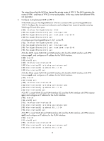
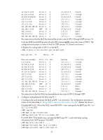
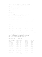
# On PE 1, enable BGP in AS 200 and specify the MCE as its EBGP peer. [PE1] bgp 200 [PE1-bgp] ip vpn-instance vpn1 [PE1-bgp-vpn1] peer 30.1.1.1 as-number 100 [PE1-bgp-vpn1] ipv4-family [PE1-bgp-ipv4-vpn1] peer 30.1.1.1 enable [PE1-bgp-ipv4-vpn1] quit [PE1-bgp-vpn1] quit [PE1-bgp] quit # On PE 1, display the routing information for VPN instance vpn1. [PE1] display ip routing-table vpn-instance vpn1 Destinations : 13 Routes : 13 Destination/Mask Proto Pre Cost NextHop Interface 0.0.0.0/32 Direct 0 0 127.0.0.1 InLoop0 30.1.1.0/24 Direct 0 0 30.1.1.2 Vlan30 30.1.1.0/32 Direct 0 0 30.1.1.2 Vlan30 30.1.1.2/32 Direct 0 0 127.0.0.1 InLoop0 30.1.1.255/32 Direct 0 0 30.1.1.2 Vlan30 127.0.0.0/8 Direct 0 0 127.0.0.1 InLoop0 127.0.0.0/32 Direct 0 0 127.0.0.1 InLoop0 127.0.0.1/32 Direct 0 0 127.0.0.1 InLoop0 127.255.255.255/32 Direct 0 0 127.0.0.1 InLoop0 192.168.0.0/24 BGP 255 3 30.1.1.1 Vlan30 224.0.0.0/4 Direct 0 0 0.0.0.0 NULL0 224.0.0.0/24 Direct 0 0 0.0.0.0 NULL0 255.255.255.255/32 Direct 0 0 127.0.0.1 InLoop0 # Perform similar configuration on the MCE and PE 1 for VPN 2. Redistribute the OSPF routes of VPN instance vpn2 into the EBGP routing table. (Details not shown.) # On PE 1, display the routing information for VPN instance vpn2. [PE1] display ip routing-table vpn-instance vpn2 Destinations : 13 Routes : 13 Destination/Mask 0.0.0.0/32 40.1.1.0/24 40.1.1.0/32 40.1.1.2/32 40.1.1.255/32 127.0.0.0/8 127.0.0.0/32 127.0.0.1/32 127.255.255.255/32 192.168.10.0/24 224.0.0.0/4 224.0.0.0/24 Proto Pre Direct 0 Direct 0 Direct 0 Direct 0 Direct 0 Direct 0 Direct 0 Direct 0 Direct 0 BGP 255 Direct 0 Direct 0 Cost 0 0 0 0 0 0 0 0 0 3 0 0 24 NextHop 127.0.0.1 40.1.1.2 40.1.1.2 127.0.0.1 40.1.1.2 127.0.0.1 127.0.0.1 127.0.0.1 127.0.0.1 40.1.1.1 0.0.0.0 0.0.0.0 Interface InLoop0 Vlan40 Vlan40 InLoop0 Vlan40 InLoop0 InLoop0 InLoop0 InLoop0 Vlan40 NULL0 NULL0
-
 1
1 -
2
-
3
-
4
-
5
-
6
-
7
-
8
-
9
-
10
-
11
-
12
-
13
-
14
-
15
-
16
-
17
-
18
-
19
-
20
-
21
-
 22
22 -
 23
23 -
 24
24 -
 25
25 -
 26
26 -
 27
27 -
 28
28 -
 29
29 -
 30
30 -
 31
31 -
 32
32 -
33
-
34
-
35
-
36
-
37
-
38
-
39
-
40
-
41
-
42
-
43
-
44
-
45
-
46
-
47
-
48
-
49
-
50
-
51
-
52
 |
 |