HP 6125XLG R2306-HP 6125XLG Blade Switch MCE Configuration Guide - Page 26
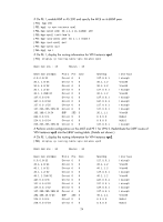
The output shows that the MCE has learned the private route of VPN 2 through OSPF.
 |
View all HP 6125XLG manuals
Add to My Manuals
Save this manual to your list of manuals |
Page 26 highlights
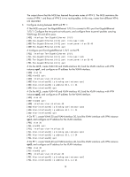
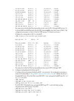
10.214.10.0/32 Direct 0 0 10.214.10.3 Vlan10 10.214.10.3/32 Direct 0 0 127.0.0.1 InLoop0 10.214.10.255/32 Direct 0 0 10.214.10.3 Vlan10 127.0.0.0/8 Direct 0 0 127.0.0.1 InLoop0 127.0.0.0/32 Direct 0 0 127.0.0.1 InLoop0 127.0.0.1/32 Direct 0 0 127.0.0.1 InLoop0 127.255.255.255/32 Direct 0 0 127.0.0.1 InLoop0 192.168.0.0/24 OSPF 10 2 10.214.10.2 Vlan10 224.0.0.0/4 Direct 0 0 0.0.0.0 NULL0 224.0.0.0/24 Direct 0 0 0.0.0.0 NULL0 255.255.255.255/32 Direct 0 0 127.0.0.1 InLoop0 The output shows that the MCE has learned the private route of VPN 1 through OSPF process 10. # On the MCE, bind OSPF process 20 with VPN instance vpn2 to learn the routes of VPN 2. The configuration procedure is similar to that for OSPF process 10. (Details not shown.) # Display the routing table of VPN 2 on the MCE. [MCE] display ip routing-table vpn-instance vpn2 Destinations : 13 Routes : 13 Destination/Mask Proto Pre Cost NextHop Interface 0.0.0.0/32 Direct 0 0 127.0.0.1 InLoop0 10.214.20.0/24 Direct 0 0 10.214.20.3 Vlan20 10.214.20.0/32 Direct 0 0 10.214.20.3 Vlan20 10.214.20.3/32 Direct 0 0 127.0.0.1 InLoop0 10.214.20.255/32 Direct 0 0 10.214.20.3 Vlan20 127.0.0.0/8 Direct 0 0 127.0.0.1 InLoop0 127.0.0.0/32 Direct 0 0 127.0.0.1 InLoop0 127.0.0.1/32 Direct 0 0 127.0.0.1 InLoop0 127.255.255.255/32 Direct 0 0 127.0.0.1 InLoop0 192.168.10.0/24 OSPF 10 2 10.214.20.2 Vlan20 224.0.0.0/4 Direct 0 0 0.0.0.0 NULL0 224.0.0.0/24 Direct 0 0 0.0.0.0 NULL0 255.255.255.255/32 Direct 0 0 127.0.0.1 InLoop0 The output shows that the MCE has learned the private route of VPN 2 through OSPF. 3. Configure routing between the MCE and PE 1: # Configure the ports between the MCE and PE 1 as trunk ports. The configuration procedure is similar to that described in "Using OSPF to advertise VPN routes to the PE." (Details not shown.) # Enable BGP in AS 100 on the MCE, enter BGP VPN 1 view, and specify the EBGP peer PE 1 at 30.1.1.2 in AS 200. [MCE] bgp 100 [MCE-bgp] ip vpn-instance vpn1 [MCE-bgp-vpn1] peer 30.1.1.2 as-number 200 # In BGP VPN 1 IPv4 family view, activate the EBGP peer PE 1, and redistribute routing information from OSPF process 10 to BGP. [MCE-bgp-vpn1] ipv4-family [MCE-bgp-ipv4-vpn1] peer 30.1.1.2 enable [MCE-bgp-ipv4-vpn1] import-route ospf 10 23
-
 1
1 -
2
-
3
-
4
-
5
-
6
-
7
-
8
-
9
-
10
-
11
-
12
-
13
-
14
-
15
-
16
-
17
-
18
-
19
-
20
-
 21
21 -
 22
22 -
 23
23 -
 24
24 -
 25
25 -
 26
26 -
 27
27 -
 28
28 -
 29
29 -
 30
30 -
 31
31 -
32
-
33
-
34
-
35
-
36
-
37
-
38
-
39
-
40
-
41
-
42
-
43
-
44
-
45
-
46
-
47
-
48
-
49
-
50
-
51
-
52
 |
 |
