HP 6531s HP Compaq 6530s, 6531s and 6535s Notebook PCs - Maintenance and Servi - Page 67
on the back of the keyboard from the switch cover, lift up the rear, edge of the keyboard
 |
View all HP 6531s manuals
Add to My Manuals
Save this manual to your list of manuals |
Page 67 highlights
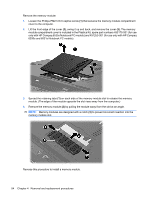
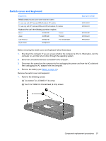
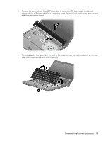
6. Release the zero insertion force (ZIF) connector to which the LED board cable is attached, disconnect the LED board cable from the system board (1), and lift the switch cover up to remove it (2) from the system board. 7. To disengage the four tabs (1) on the back of the keyboard from the switch cover, lift up the rear edge of the keyboard (2), and slide it back (3). Component replacement procedures 59
-
 1
1 -
2
-
3
-
4
-
5
-
6
-
7
-
8
-
9
-
10
-
11
-
12
-
13
-
14
-
15
-
16
-
17
-
18
-
19
-
20
-
21
-
22
-
23
-
24
-
25
-
26
-
27
-
28
-
29
-
30
-
31
-
32
-
33
-
34
-
35
-
36
-
37
-
38
-
39
-
40
-
41
-
42
-
43
-
44
-
45
-
46
-
47
-
48
-
49
-
50
-
51
-
52
-
53
-
54
-
55
-
56
-
57
-
58
-
59
-
60
-
61
-
 62
62 -
 63
63 -
 64
64 -
 65
65 -
 66
66 -
 67
67 -
 68
68 -
 69
69 -
 70
70 -
 71
71 -
 72
72 -
73
-
74
-
75
-
76
-
77
-
78
-
79
-
80
-
81
-
82
-
83
-
84
-
85
-
86
-
87
-
88
-
89
-
90
-
91
-
92
-
93
-
94
-
95
-
96
-
97
-
98
-
99
-
100
-
101
-
102
-
103
-
104
-
105
-
106
-
107
-
108
-
109
-
110
-
111
-
112
-
113
-
114
-
115
-
116
-
117
-
118
-
119
-
120
-
121
-
122
-
123
-
124
-
125
-
126
-
127
-
128
-
129
-
130
-
131
-
132
-
133
-
134
-
135
-
136
-
137
-
138
-
139
-
140
-
141
-
142
-
143
-
144
-
145
-
146
-
147
-
148
-
149
-
150
-
151
-
152
-
153
-
154
-
155
-
156
-
157
-
158
-
159
-
160
-
161
 |
 |
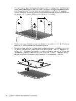
6.
Release the zero insertion force (ZIF) connector to which the LED board cable is attached,
disconnect the LED board cable from the system board
(1)
, and lift the switch cover up to remove
it
(2)
from the system board.
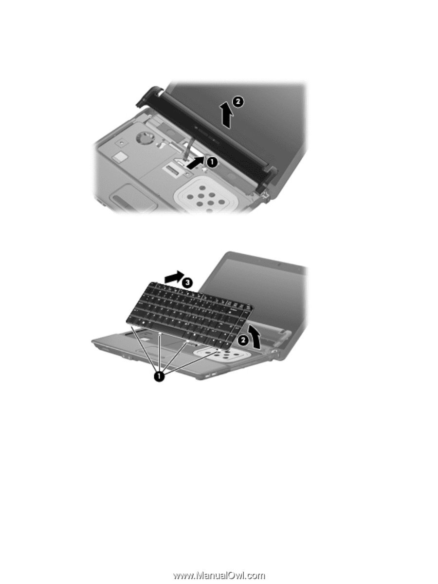
7.
To disengage the four tabs
(1)
on the back of the keyboard from the switch cover, lift up the rear
edge of the keyboard
(2)
, and slide it back
(3)
.
Component replacement procedures
59