HP 6531s HP Compaq 6530s, 6531s and 6535s Notebook PCs - Maintenance and Servi - Page 71
CAUTION, that is secured to the left hinge.
 |
View all HP 6531s manuals
Add to My Manuals
Save this manual to your list of manuals |
Page 71 highlights
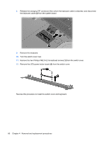
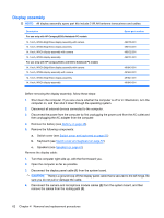
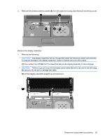
5. Remove the wireless antenna cables (4) from the clips and routing channels built into the top cover. Remove the display assembly: 1. Remove the following: CAUTION: The display assembly will be unsupported when the following screws are removed. To prevent damage to the display assembly, support it before removing the screws. (1) Four slotted Torx ST8M2.5×7.0 screws that secure the display assembly to the computer. CAUTION: There is a ground loop off the display panel cable (2) that is secured to the left hinge. Be sure you do not pull or damage the cable. (3) Lift the display assembly straight up and remove it. Component replacement procedures 63
-
 1
1 -
2
-
3
-
4
-
5
-
6
-
7
-
8
-
9
-
10
-
11
-
12
-
13
-
14
-
15
-
16
-
17
-
18
-
19
-
20
-
21
-
22
-
23
-
24
-
25
-
26
-
27
-
28
-
29
-
30
-
31
-
32
-
33
-
34
-
35
-
36
-
37
-
38
-
39
-
40
-
41
-
42
-
43
-
44
-
45
-
46
-
47
-
48
-
49
-
50
-
51
-
52
-
53
-
54
-
55
-
56
-
57
-
58
-
59
-
60
-
61
-
62
-
63
-
64
-
65
-
 66
66 -
 67
67 -
 68
68 -
 69
69 -
 70
70 -
 71
71 -
 72
72 -
 73
73 -
 74
74 -
 75
75 -
 76
76 -
77
-
78
-
79
-
80
-
81
-
82
-
83
-
84
-
85
-
86
-
87
-
88
-
89
-
90
-
91
-
92
-
93
-
94
-
95
-
96
-
97
-
98
-
99
-
100
-
101
-
102
-
103
-
104
-
105
-
106
-
107
-
108
-
109
-
110
-
111
-
112
-
113
-
114
-
115
-
116
-
117
-
118
-
119
-
120
-
121
-
122
-
123
-
124
-
125
-
126
-
127
-
128
-
129
-
130
-
131
-
132
-
133
-
134
-
135
-
136
-
137
-
138
-
139
-
140
-
141
-
142
-
143
-
144
-
145
-
146
-
147
-
148
-
149
-
150
-
151
-
152
-
153
-
154
-
155
-
156
-
157
-
158
-
159
-
160
-
161
 |
 |
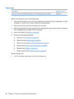
5.
Remove the wireless antenna cables
(4)
from the clips and routing channels built into the top cover.
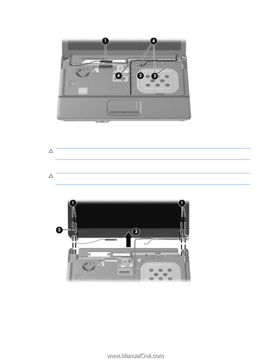
Remove the display assembly:
1.
Remove the following:
CAUTION:
The display assembly will be unsupported when the following screws are removed.
To prevent damage to the display assembly, support it before removing the screws.
(1)
Four slotted Torx ST8M2.5×7.0 screws that secure the display assembly to the computer.
CAUTION:
There is a ground loop off the display panel cable
(2)
that is secured to the left hinge.
Be sure you do not pull or damage the cable.
(3)
Lift the display assembly straight up and remove it.
Component replacement procedures
63