HP 6531s HP Compaq 6530s, 6531s and 6535s Notebook PCs - Maintenance and Servi - Page 70
Display assembly
 |
View all HP 6531s manuals
Add to My Manuals
Save this manual to your list of manuals |
Page 70 highlights
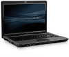
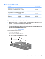
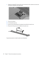
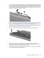
Display assembly NOTE: All display assembly spare part kits include 2 WLAN antenna transceivers and cables. Description For use only with HP Compaq 6535s Notebook PC models 14.1-inch, WXGA BrightView display assembly with camera 14.1-inch, WXGA BrightView display assembly 14.1-inch, WXGA display assembly with camera 14.1-inch, WXGA display assembly For use only with HP Compaq 6530s and 6531s Notebook PC models 14.1-inch, WXGA BrightView display assembly with camera 14.1-inch, WXGA display assembly with camera 14.1-inch, WXGA BrightView display assembly 14.1-inch, WXGA display assembly Spare part number 493155-001 493154-001 493152-001 493151-001 491643-001 491642-001 491641-001 491640-001 Before removing the display assembly, follow these steps: 1. Shut down the computer. If you are unsure whether the computer is off or in Hibernation, turn the computer on, and then shut it down through the operating system. 2. Disconnect all external devices connected to the computer. 3. Disconnect the power from the computer by first unplugging the power cord from the AC outlet and then unplugging the AC adapter from the computer. 4. Remove the battery (see Battery on page 46). 5. Remove the following components: a. Switch cover (see Switch cover and keyboard on page 57) b. Keyboard (see Switch cover and keyboard on page 57) c. Speakers (see Speakers on page 61) Remove the display cable: 1. Turn the computer right-side up, with the front toward you. 2. Open the computer as far as possible. 3. Disconnect the display panel cable (1) from the system board. CAUTION: There is a ground loop off the display panel cable that is secured to the left hinge. Be sure you do not pull or damage the cable. 4. Disconnect the camera and microphone module cables (2) from the system board, and then remove the cables from the routing path (3). 62 Chapter 4 Removal and replacement procedures
-
 1
1 -
2
-
3
-
4
-
5
-
6
-
7
-
8
-
9
-
10
-
11
-
12
-
13
-
14
-
15
-
16
-
17
-
18
-
19
-
20
-
21
-
22
-
23
-
24
-
25
-
26
-
27
-
28
-
29
-
30
-
31
-
32
-
33
-
34
-
35
-
36
-
37
-
38
-
39
-
40
-
41
-
42
-
43
-
44
-
45
-
46
-
47
-
48
-
49
-
50
-
51
-
52
-
53
-
54
-
55
-
56
-
57
-
58
-
59
-
60
-
61
-
62
-
63
-
64
-
 65
65 -
 66
66 -
 67
67 -
 68
68 -
 69
69 -
 70
70 -
 71
71 -
 72
72 -
 73
73 -
 74
74 -
 75
75 -
76
-
77
-
78
-
79
-
80
-
81
-
82
-
83
-
84
-
85
-
86
-
87
-
88
-
89
-
90
-
91
-
92
-
93
-
94
-
95
-
96
-
97
-
98
-
99
-
100
-
101
-
102
-
103
-
104
-
105
-
106
-
107
-
108
-
109
-
110
-
111
-
112
-
113
-
114
-
115
-
116
-
117
-
118
-
119
-
120
-
121
-
122
-
123
-
124
-
125
-
126
-
127
-
128
-
129
-
130
-
131
-
132
-
133
-
134
-
135
-
136
-
137
-
138
-
139
-
140
-
141
-
142
-
143
-
144
-
145
-
146
-
147
-
148
-
149
-
150
-
151
-
152
-
153
-
154
-
155
-
156
-
157
-
158
-
159
-
160
-
161
 |
 |