HP 6531s HP Compaq 6530s, 6531s and 6535s Notebook PCs - Maintenance and Servi - Page 87
System board, Switch cover see
 |
View all HP 6531s manuals
Add to My Manuals
Save this manual to your list of manuals |
Page 87 highlights
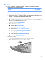
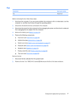
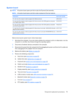
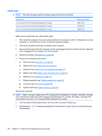
System board NOTE: All system board spare part kits include the ExpressCard assembly. NOTE: All system board spare part kits include replacement thermal material. Description Spare part number For use only with computer models equipped with AMD processors 497613-001 For use only with computer models equipped with Intel processors with UMA graphics subsystem 501354-001 and a GM45 system board For use only with computer models equipped with Intel processors with UMA graphics subsystem 491250-001 and a GL40 system board For use only with computer models equipped with Intel processors (includes 128-MB DDR2 discrete 491977-001 graphics system memory) For use only with computer models equipped with Intel processors (includes 256-MB DDR2 discrete 491976-001 graphics system memory) Before removing the system board, follow these steps: 1. Shut down the computer. If you are unsure whether the computer is off or in Hibernation, turn the computer on, and then shut it down through the operating system. 2. Disconnect all external devices connected to the computer. 3. Disconnect the power from the computer by first unplugging the power cord from the AC outlet and then unplugging the AC adapter from the computer. 4. Remove the battery (see Battery on page 46). 5. Remove the following components: a. Hard drive (see Hard drive on page 47) b. Optical drive (see Optical drive on page 55) c. Keyboard (see Switch cover and keyboard on page 57) d. Switch cover (see Switch cover and keyboard on page 57) e. Speakers (see Speakers on page 61) f. Display assembly (see Display assembly on page 62) g. Top cover (see Top cover on page 68) h. USB connector module (see USB connector module on page 72) i. Bluetooth module (see Bluetooth module on page 73) j. Fan (see Fan on page 77) k. RTC battery (see RTC battery on page 75) Component replacement procedures 79
-
 1
1 -
2
-
3
-
4
-
5
-
6
-
7
-
8
-
9
-
10
-
11
-
12
-
13
-
14
-
15
-
16
-
17
-
18
-
19
-
20
-
21
-
22
-
23
-
24
-
25
-
26
-
27
-
28
-
29
-
30
-
31
-
32
-
33
-
34
-
35
-
36
-
37
-
38
-
39
-
40
-
41
-
42
-
43
-
44
-
45
-
46
-
47
-
48
-
49
-
50
-
51
-
52
-
53
-
54
-
55
-
56
-
57
-
58
-
59
-
60
-
61
-
62
-
63
-
64
-
65
-
66
-
67
-
68
-
69
-
70
-
71
-
72
-
73
-
74
-
75
-
76
-
77
-
78
-
79
-
80
-
81
-
 82
82 -
 83
83 -
 84
84 -
 85
85 -
 86
86 -
 87
87 -
 88
88 -
 89
89 -
 90
90 -
 91
91 -
 92
92 -
93
-
94
-
95
-
96
-
97
-
98
-
99
-
100
-
101
-
102
-
103
-
104
-
105
-
106
-
107
-
108
-
109
-
110
-
111
-
112
-
113
-
114
-
115
-
116
-
117
-
118
-
119
-
120
-
121
-
122
-
123
-
124
-
125
-
126
-
127
-
128
-
129
-
130
-
131
-
132
-
133
-
134
-
135
-
136
-
137
-
138
-
139
-
140
-
141
-
142
-
143
-
144
-
145
-
146
-
147
-
148
-
149
-
150
-
151
-
152
-
153
-
154
-
155
-
156
-
157
-
158
-
159
-
160
-
161
 |
 |