HP 6531s HP Compaq 6530s, 6531s and 6535s Notebook PCs - Maintenance and Servi - Page 68
from the switch cover., Remove the LED power button board
 |
View all HP 6531s manuals
Add to My Manuals
Save this manual to your list of manuals |
Page 68 highlights
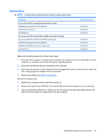
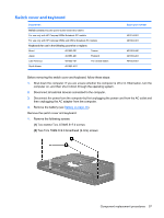
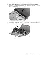
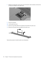
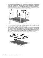
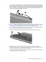
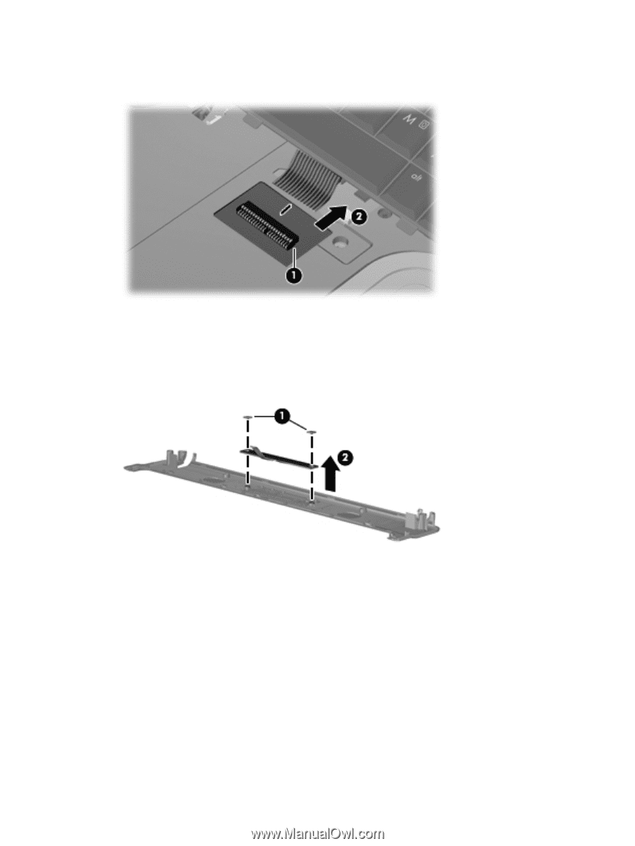
8. Release the swinging ZIF connector (1) to which the keyboard cable is attached, and disconnect the keyboard cable (2) from the system board. 9. Remove the keyboard. 10. Turn the switch cover over. 11. Remove the two Phillips PM2.0×2.0 broadhead screws (1) from the switch cover. 12. Remove the LED power button board (2) from the switch cover. Reverse this procedure to install the switch cover and keyboard. 60 Chapter 4 Removal and replacement procedures
-
 1
1 -
2
-
3
-
4
-
5
-
6
-
7
-
8
-
9
-
10
-
11
-
12
-
13
-
14
-
15
-
16
-
17
-
18
-
19
-
20
-
21
-
22
-
23
-
24
-
25
-
26
-
27
-
28
-
29
-
30
-
31
-
32
-
33
-
34
-
35
-
36
-
37
-
38
-
39
-
40
-
41
-
42
-
43
-
44
-
45
-
46
-
47
-
48
-
49
-
50
-
51
-
52
-
53
-
54
-
55
-
56
-
57
-
58
-
59
-
60
-
61
-
62
-
 63
63 -
 64
64 -
 65
65 -
 66
66 -
 67
67 -
 68
68 -
 69
69 -
 70
70 -
 71
71 -
 72
72 -
 73
73 -
74
-
75
-
76
-
77
-
78
-
79
-
80
-
81
-
82
-
83
-
84
-
85
-
86
-
87
-
88
-
89
-
90
-
91
-
92
-
93
-
94
-
95
-
96
-
97
-
98
-
99
-
100
-
101
-
102
-
103
-
104
-
105
-
106
-
107
-
108
-
109
-
110
-
111
-
112
-
113
-
114
-
115
-
116
-
117
-
118
-
119
-
120
-
121
-
122
-
123
-
124
-
125
-
126
-
127
-
128
-
129
-
130
-
131
-
132
-
133
-
134
-
135
-
136
-
137
-
138
-
139
-
140
-
141
-
142
-
143
-
144
-
145
-
146
-
147
-
148
-
149
-
150
-
151
-
152
-
153
-
154
-
155
-
156
-
157
-
158
-
159
-
160
-
161
 |
 |
8.
Release the swinging ZIF connector
(1)
to which the keyboard cable is attached, and disconnect
the keyboard cable
(2)
from the system board.
9.
Remove the keyboard.
10.
Turn the switch cover over.
11.
Remove the two Phillips PM2.0×2.0 broadhead screws
(1)
from the switch cover.
12.
Remove the LED power button board
(2)
from the switch cover.
Reverse this procedure to install the switch cover and keyboard.
60
Chapter 4
Removal and replacement procedures