HP 6531s HP Compaq 6530s, 6531s and 6535s Notebook PCs - Maintenance and Servi - Page 77
Remove the three Phillips PM2.0×2.0 broadhead 5-mm screws from the optical drive bay
 |
View all HP 6531s manuals
Add to My Manuals
Save this manual to your list of manuals |
Page 77 highlights
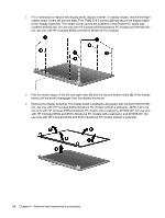
2. Remove the two rubber screw covers (1) and the seven slotted Torx ST8M2.5×7.0 screws (2) that secure the top cover to the computer. The rubber screw covers are available in the Rubber Kit, spare part numbers 497622-001 (for use only with HP Compaq 6535s Notebook PC models) and 491654-001 (for use only with HP Compaq 6530s and 6531s Notebook PC models). 3. Remove the three Phillips PM2.0×2.0 broadhead (5-mm) screws from the optical drive bay (1), and remove the Torx T8M2.5x4.0 screw from the hard drive bay (2). 4. Turn the computer right-side up. Component replacement procedures 69
-
 1
1 -
2
-
3
-
4
-
5
-
6
-
7
-
8
-
9
-
10
-
11
-
12
-
13
-
14
-
15
-
16
-
17
-
18
-
19
-
20
-
21
-
22
-
23
-
24
-
25
-
26
-
27
-
28
-
29
-
30
-
31
-
32
-
33
-
34
-
35
-
36
-
37
-
38
-
39
-
40
-
41
-
42
-
43
-
44
-
45
-
46
-
47
-
48
-
49
-
50
-
51
-
52
-
53
-
54
-
55
-
56
-
57
-
58
-
59
-
60
-
61
-
62
-
63
-
64
-
65
-
66
-
67
-
68
-
69
-
70
-
71
-
 72
72 -
 73
73 -
 74
74 -
 75
75 -
 76
76 -
 77
77 -
 78
78 -
 79
79 -
 80
80 -
 81
81 -
 82
82 -
83
-
84
-
85
-
86
-
87
-
88
-
89
-
90
-
91
-
92
-
93
-
94
-
95
-
96
-
97
-
98
-
99
-
100
-
101
-
102
-
103
-
104
-
105
-
106
-
107
-
108
-
109
-
110
-
111
-
112
-
113
-
114
-
115
-
116
-
117
-
118
-
119
-
120
-
121
-
122
-
123
-
124
-
125
-
126
-
127
-
128
-
129
-
130
-
131
-
132
-
133
-
134
-
135
-
136
-
137
-
138
-
139
-
140
-
141
-
142
-
143
-
144
-
145
-
146
-
147
-
148
-
149
-
150
-
151
-
152
-
153
-
154
-
155
-
156
-
157
-
158
-
159
-
160
-
161
 |
 |
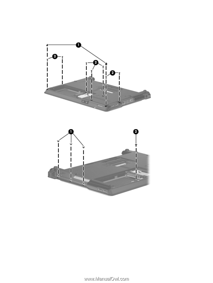
2.
Remove the two rubber screw covers
(1)
and the seven slotted Torx ST8M2.5×7.0 screws
(2)
that
secure the top cover to the computer. The rubber screw covers are available in the Rubber Kit,
spare part numbers 497622-001 (for use only with HP Compaq 6535s Notebook PC models) and
491654-001 (for use only with HP Compaq 6530s and 6531s Notebook PC models).
3.
Remove the three Phillips PM2.0×2.0 broadhead (5-mm) screws from the optical drive bay
(1)
, and
remove the Torx T8M2.5x4.0 screw from the hard drive bay
(2)
.
4.
Turn the computer right-side up.
Component replacement procedures
69