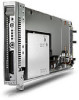
HP BladeSystem bc2800 Service Reference Guide: HP BladeSystem PC Blade Enclosu
HP BladeSystem bc2800 - Blade PC Manual
 |
View all HP BladeSystem bc2800 manuals
Add to My Manuals
Save this manual to your list of manuals |
HP BladeSystem bc2800 manual content summary:
- HP BladeSystem bc2800 | Service Reference Guide: HP BladeSystem PC Blade Enclosu - Page 1
Service Reference Guide HP BladeSystem PC Blade Enclosure G2 Assemblies - HP BladeSystem bc2800 | Service Reference Guide: HP BladeSystem PC Blade Enclosu - Page 2
HP products and services are set forth in the express warranty statements accompanying such products and services. Nothing herein should be construed as constituting an additional warranty. HP Hewlett-Packard Company. Service Reference Guide Business PCs First Edition (February 2009) Document Part - HP BladeSystem bc2800 | Service Reference Guide: HP BladeSystem PC Blade Enclosu - Page 3
Table of contents 1 About this Guide ...1 Audience Assumptions ...1 Technician Notes ...1 Where to Go or Additional Help ...2 2 Illustrated Parts Catalog ...3 HP BladeSystem PC Blade Enclosure Components (Exploded View 3 3 Removal and Replacement Procedures ...5 Safety Considerations ...5 - HP BladeSystem bc2800 | Service Reference Guide: HP BladeSystem PC Blade Enclosu - Page 4
40 Fan Health LEDs ...41 HP Blade PC and Diagnostic Adapter LEDs 42 6 POST Error Messages ...44 7 Troubleshooting ...49 When the enclosure does not start ...50 Enclosure diagnostic steps ...51 When the Blade PC Does Not Start 57 Blade PC Diagnostic Steps ...58 Problems After Initial Boot ...63 - HP BladeSystem bc2800 | Service Reference Guide: HP BladeSystem PC Blade Enclosu - Page 5
Command Line Interface 66 Powering Off the Blade PC 66 Web-Based Interface 66 Command Line Interface 67 Reviewing the Integrated Administrator System Log 67 Web-Based Interface 67 Command Line Interface 67 8 Specifications ...68 Blade Enclosure ...68 Blade PC ...69 Hot-Plug Power Supply ...70 - HP BladeSystem bc2800 | Service Reference Guide: HP BladeSystem PC Blade Enclosu - Page 6
vi - HP BladeSystem bc2800 | Service Reference Guide: HP BladeSystem PC Blade Enclosu - Page 7
Guide Use this service reference guide when servicing HP BladeSystem PC Blade Enclosure G2 assemblies. WARNING! To reduce the risk of personal injury from electric shock and hazardous energy levels, only authorized service by HP should attempt to repair this equipment. All troubleshooting and - HP BladeSystem bc2800 | Service Reference Guide: HP BladeSystem PC Blade Enclosu - Page 8
advisories and bulletins ● QuickFind information services ● HP Systems Insight Manager ● Integrated Administrator user guide ● Quickspecs ● HP BladeSystem bc2000/bc2500 Blade PC and HP BladeSystem bc2200/bc2800 Blade PC Service Reference Guide For HP technical support ● In the United States and - HP BladeSystem bc2800 | Service Reference Guide: HP BladeSystem PC Blade Enclosu - Page 9
2 Illustrated Parts Catalog HP BladeSystem PC Blade Enclosure Components (Exploded View) Figure 2-1 Enclosure components For detailed information about the blade PC, see http://bizsupport.austin.hp.com/bc/docs/support/ SupportManual/c01091959/c01091959.pdf. Table 2-1 Spare Parts List Item - HP BladeSystem bc2800 | Service Reference Guide: HP BladeSystem PC Blade Enclosu - Page 10
(continued) 4 Fan backplane assembly with cable 5 Fan cage 6 Hot-plug fan, 80 mm 7 Enclosure status assembly 8 HP PC Blade Switch assembly (with IA board) 9 HP PC Blade RJ-45 Patch Panel assembly (with IA board) *Not shown 510553-001 n/a 417425-001 n/a n/a n/a 4 Chapter 2 Illustrated - HP BladeSystem bc2800 | Service Reference Guide: HP BladeSystem PC Blade Enclosu - Page 11
procedures for HP PC Blade Enclosures with reference to HP Blade PCs. Safety Considerations Before performing service procedures, documentation for specific details. This symbol indicates the presence of hazardous energy circuits or electric shock hazards. Refer all servicing to qualified personnel - HP BladeSystem bc2800 | Service Reference Guide: HP BladeSystem PC Blade Enclosu - Page 12
area contains no user or field serviceable parts. Do not open for health and safety requirements and guidelines for manual material handling. Rack Warnings and Cautions in multiple rack installations. WARNING! When installing the HP PC Blade Enclosure in a Telco rack, adequately secure the rack - HP BladeSystem bc2800 | Service Reference Guide: HP BladeSystem PC Blade Enclosu - Page 13
both personnel and property. Heed all cautions and warnings throughout the installation instructions that came with the enclosure. WARNING! There is a risk of injury Hot-plug components in the HP BladeSystem PC Blade Enclosure include: ● Hot-plug power supplies ● Hot-plug fans Hot-Plug Procedures - HP BladeSystem bc2800 | Service Reference Guide: HP BladeSystem PC Blade Enclosu - Page 14
used in the HP PC Blade Enclosure G2. No other power supply may be used. Attempting to use a different power supply in the HP PC blade Enclosure G2, or to identify a failed power supply. Refer to the HP Integrated Administrator User Guide for details. To remove a redundant hot-plug power - HP BladeSystem bc2800 | Service Reference Guide: HP BladeSystem PC Blade Enclosu - Page 15
Hot-Plug Fans NOTE: You can use the Integrated Administrator to identify a failed hot-plug fan. Refer to the HP Integrated Administrator User Guide for details. To remove a hot-plug fan: 1. Press the release latch on the fan cage (1). 2. Pull the fan cage out of the enclosure until it - HP BladeSystem bc2800 | Service Reference Guide: HP BladeSystem PC Blade Enclosu - Page 16
perform a graceful shutdown of an HP BladeSystem PC Blade Enclosure by using the POWEROFF ENCLOSURE command in the Integrated Administrator. To power down the enclosure using the Integrated Administrator, refer to the HP Integrated Administrator User Guide. CAUTION: If the Integrated Administrator - HP BladeSystem bc2800 | Service Reference Guide: HP BladeSystem PC Blade Enclosu - Page 17
using the Integrated Administrator, refer to the HP Integrated Administrator User Guide for detailed instructions. Pressing and Holding the Enclosure Power Button You can also perform an emergency shutdown of an HP BladeSystem PC Blade Enclosure and all HP Blade PCs by pressing and holding the power - HP BladeSystem bc2800 | Service Reference Guide: HP BladeSystem PC Blade Enclosu - Page 18
is active, notify the users and stop applications as necessary. 3. Shut down the operating system. This may shut off the blade PC power. 4. If the blade PC still has power, power down the blade PC by either: ● Using the Integrated Administrator, or ● Pressing the power button (6) on the front of the - HP BladeSystem bc2800 | Service Reference Guide: HP BladeSystem PC Blade Enclosu - Page 19
. For more information, see the Service Reference Guide at http://bizsupport.austin.hp.com/bc/docs/ support/SupportManual/c01091959/c01091959.pdf. CAUTION: Integrated Administrator security settings are assigned to HP Blade PC bays, not to HP Blade PCs. If HP Blade PCs change locations within the - HP BladeSystem bc2800 | Service Reference Guide: HP BladeSystem PC Blade Enclosu - Page 20
events, be sure that each HP Blade PC bay contains an HP Blade PC or HP Blade PC blank bezel while the enclosure is powered up. To remove the HP Blade PC blank bezel: 1. Press the ejector tabs on the HP Blade PC blank bezel (1). 2. Remove the HP Blade PC blank bezel from the enclosure (2). Figure - HP BladeSystem bc2800 | Service Reference Guide: HP BladeSystem PC Blade Enclosu - Page 21
Removing the Interconnect Tray To remove the interconnect tray: 1. Power down each HP Blade PC (Powering Down a Blade PC on page 12). 2. Power down the enclosure (Powering Down the Enclosure on page 10). 3. Disconnect all cables and power cords from the AC power source. 4. - HP BladeSystem bc2800 | Service Reference Guide: HP BladeSystem PC Blade Enclosu - Page 22
cords from the AC power source. 4. Disconnect all cables and power cords from the enclosure rear panel. 5. Remove all HP Blade PCs and HP Blade PC blank bezels (Removing an HP Blade PC Blank Bezel on page 14). 6. Remove both hot-plug power supplies (Hot-Plug Power Supplies on page 8). 7. Remove the - HP BladeSystem bc2800 | Service Reference Guide: HP BladeSystem PC Blade Enclosu - Page 23
security settings are assigned to HP PC Blade Enclosure bays, not to HP Blade PCs. If HP Blade PCs change locations within the enclosure, Integrated Administrator settings must also be adjusted to ensure accurate security. Refer to the HP Integrated Administrator User Guide for more information on - HP BladeSystem bc2800 | Service Reference Guide: HP BladeSystem PC Blade Enclosu - Page 24
-Plug Procedures Before removing or replacing non-hot-plug components, you must power down the HP PC Blade Enclosure completely. Non-hot-plug components in the HP BladeSystem PC Blade Enclosure system include: ● Fan cage ● Fan backplane assembly ● Interconnect tray ● Integrated Administrator module - HP BladeSystem bc2800 | Service Reference Guide: HP BladeSystem PC Blade Enclosu - Page 25
security settings are assigned to HP PC Blade Enclosure bays, not to HP Blade PCs. If HP Blade PCs change locations within the enclosure, Integrated Administrator settings must also be adjusted to ensure accurate security. Refer to the HP Integrated Administrator User Guide for more information on - HP BladeSystem bc2800 | Service Reference Guide: HP BladeSystem PC Blade Enclosu - Page 26
removal procedure is the same for both types of interconnect trays. To remove the Integrated Administrator module: 1. Power down each HP Blade PC (Powering Down a Blade PC on page 12). 2. Power down the enclosure (Powering Down the Enclosure on page 10). 3. Disconnect all cables and power cords - HP BladeSystem bc2800 | Service Reference Guide: HP BladeSystem PC Blade Enclosu - Page 27
settings are assigned to HP PC Blade Enclosure bays, not to HP Blade PCs. If HP Blade PCs change locations within the enclosure, Integrated Administrator settings must also be adjusted to ensure accurate security. Refer to the HP Integrated Administrator User Guide for more information about - HP BladeSystem bc2800 | Service Reference Guide: HP BladeSystem PC Blade Enclosu - Page 28
9. Place the enclosure on a level, non-conductive surface. 10. Open the access door (Opening the Access Door on page 17). 11. Disconnect the enclosure status cable from the midplane (signal board). Figure 3-15 Disconnecting the enclosure status cable from the midplane signal board 12. Remove the - HP BladeSystem bc2800 | Service Reference Guide: HP BladeSystem PC Blade Enclosu - Page 29
security settings are assigned to HP PC Blade Enclosure bays, not to HP Blade PCs. If HP Blade PCs change locations within the enclosure, Integrated Administrator settings must also be adjusted to ensure accurate security. Refer to the HP Integrated Administrator User Guide for more information on - HP BladeSystem bc2800 | Service Reference Guide: HP BladeSystem PC Blade Enclosu - Page 30
14. Remove the midplane assembly from the enclosure (2). Figure 3-17 Removing the midplane assembly from the enclosure Reverse the previous steps to replace the midplane assembly. Swapping the Interconnect Tray To swap the existing interconnect tray with a replacement interconnect tray: 1. Remove - HP BladeSystem bc2800 | Service Reference Guide: HP BladeSystem PC Blade Enclosu - Page 31
7. Secure the two hold down clamps to the opposite edges of the Integrated Administrator board, and then tighten the two screws (4). NOTE: The Integrated Administrator board is spared as part of the interconnect tray assembly within the standard warranty period. Figure 3-18 Installing the Integrated - HP BladeSystem bc2800 | Service Reference Guide: HP BladeSystem PC Blade Enclosu - Page 32
provides keyboard and mouse capability for an HP Blade PC, regardless of the state of the host operating system or host HP Blade PC. Use the following tools to diagnose problems, test hardware, and monitor and manage HP BladeSystem PC Blade system operations. Table 4-1 Diagnostic tools Tool - HP BladeSystem bc2800 | Service Reference Guide: HP BladeSystem PC Blade Enclosu - Page 33
the event list, refer to the Management CD or the SIM User Guide. ROM-Based Setup Utility (RBSU) RBSU configures the hardware installed in or connected to the HP Blade PC. Specifically, it can: ● Store configuration information in nonvolatile memory. ● Manage memory installation, processor - HP BladeSystem bc2800 | Service Reference Guide: HP BladeSystem PC Blade Enclosu - Page 34
pictured (obsolete) 4. Power up the HP Blade PC. NOTE: Because PS/2 devices do not support hot-plug technology, restart the HP Blade PC after attaching the diagnostic adapter. USB devices are hot-plug supported and do not require restarting the HP Blade PC after attachment. Table 4-2 Cable Pin - HP BladeSystem bc2800 | Service Reference Guide: HP BladeSystem PC Blade Enclosu - Page 35
GND 5 DSR 6 CD 1 DB 9 PIN 2 3 8 7 5 4 4 DB 25 PIN 3 2 5 4 7 20 20 Null-Modem Cable Pin-Out Use the above table(s) to determine the specifications of the cable(s). If you are cabling a serial device (such as a laptop computer) to the console connector on the Integrated Administrator, be sure - HP BladeSystem bc2800 | Service Reference Guide: HP BladeSystem PC Blade Enclosu - Page 36
and HP BladeSystem PC Blade Enclosures. Enclosure Connectors This section explains the location and function of rear panel connectors associated with the HP PC Blade Switch and RJ-45 patch panel interconnect tray. Interconnect Switch Connectors Figure 5-1 HP PC Blade Switch connectors NOTE: bc2800 - HP BladeSystem bc2800 | Service Reference Guide: HP BladeSystem PC Blade Enclosu - Page 37
for HP PC Blade Enclosure bay 1 NIC B (2) *These items denote connectors for the Integrated Administrator module. Location RJ-45 patch panel RJ-45 patch panel Integrated Administrator module Integrated Administrator module RJ-45 patch panel RJ-45 patch panel CAUTION: See QuickSpecs for supported - HP BladeSystem bc2800 | Service Reference Guide: HP BladeSystem PC Blade Enclosu - Page 38
fan cable. Figure 5-3 Fan cable connector on the midplane assembly Enclosure Status Cable Connector This section identifies the connector on the HP PC Blade Enclosure midplane for the enclosure status cable. Figure 5-4 Enclosure status cable connector on the midplane assembly 32 Chapter 5 Connectors - HP BladeSystem bc2800 | Service Reference Guide: HP BladeSystem PC Blade Enclosu - Page 39
This section identifies the connectors on each HP Blade PC. Figure 5-5 Identifying the HP Blade PC connectors Item 1 2 Description Midplane assembly connectors Diagnostic connector Diagnostic Adapter Connectors (USB 1.1 and USB 2.0) This section identifies the connectors on the diagnostic - HP BladeSystem bc2800 | Service Reference Guide: HP BladeSystem PC Blade Enclosu - Page 40
This section identifies the connectors on the diagnostic adapter version USB 2.0 Figure 5-7 Diagnostic adapter connectors USB 2.0 version Item 1 2 3 4 5 6 Description Keyboard connector (PS/2) Mouse connector (PS/2) Serial connector Video connector USB 2.0 connector #1 USB 2.0 connector #2 34 - HP BladeSystem bc2800 | Service Reference Guide: HP BladeSystem PC Blade Enclosu - Page 41
the switches on the front panel of the enclosure and HP Blade PC. Figure 5-8 HP Blade PC and enclosure front panel buttons Item 1 2 3 Description HP Blade PC unit identification button Enclosure unit identification button HP Blade PC power button Function Activates the unit identification LED for - HP BladeSystem bc2800 | Service Reference Guide: HP BladeSystem PC Blade Enclosu - Page 42
the enclosure. Figure 5-9 Enclosure rear panel buttons NOTE: bc2800 shown. Item 1 Description Enclosure unit identification button 2 and all HP Blade PCs, and may result in the loss of any unsaved data on all HP Blade PCs. CMOS Press the CMOS button (labeled SW50) on the blade PC's system board - HP BladeSystem bc2800 | Service Reference Guide: HP BladeSystem PC Blade Enclosu - Page 43
LEDs The figures and tables on the following pages show the location and function of LEDs associated with the HP BladeSystem PC Blade system. Enclosure Front Panel LEDs Figure 5-10 Enclosure front panel LEDs Table 5-1 Enclosure Front Panel LEDs Item LED 1 Enclosure unit ID (unit identification) - HP BladeSystem bc2800 | Service Reference Guide: HP BladeSystem PC Blade Enclosu - Page 44
. Rear panel LEDs with HP PC Blade Switch Figure 5-11 Rear panel LEDs with the HP PC Blade Switch NOTE: bc2800 shown. This section identifies the LEDs on the enclosure rear panel with an HP PC Blade Switch . Table 5-2 Rear panel LEDs with the HP PC Blade Switch Item LED Status Description - HP BladeSystem bc2800 | Service Reference Guide: HP BladeSystem PC Blade Enclosu - Page 45
Table 5-2 Rear panel LEDs with the HP PC Blade Switch (continued) 6 Integrated Administrator health Off Enclosure off, Integrated Administrator health good Green Enclosure on, Integrated Administrator health good Amber Integrated Administrator critical 7 Interconnect switch - HP BladeSystem bc2800 | Service Reference Guide: HP BladeSystem PC Blade Enclosu - Page 46
Rear Panel LEDs with RJ-45 Patch Panel Interconnect Tray Figure 5-12 Rear panel LEDs with RJ-45 patch panel interconnect tray Item 1 2 3 4 5 6 7 LED Power supply power Power supply fault Enclosure power Fan health Enclosure unit identification RJ-45 link/activity Integrated Administrator health - HP BladeSystem bc2800 | Service Reference Guide: HP BladeSystem PC Blade Enclosu - Page 47
Fan Health LEDs This section identifies the LEDs on the hot-plug fans. Figure 5-13 Hot-plug fan health LEDs NOTE: bc2800 shown. Table 5-3 Hot-Plug Fan Health LEDs Item LED 1 Fan 1 2 Fan 2 3 Fan 3 4 Fan 4 Green = Normal Amber = Failed LEDs 41 - HP BladeSystem bc2800 | Service Reference Guide: HP BladeSystem PC Blade Enclosu - Page 48
Red Off Green Description Unit not identified Identification of HP Blade PC HP Blade PC off and health last good HP Blade PC on and health good HP Blade PC degraded, or power-up prohibited by the Integrated Administrator HP Blade PC critical No connection Linked to network 42 Chapter 5 Connectors - HP BladeSystem bc2800 | Service Reference Guide: HP BladeSystem PC Blade Enclosu - Page 49
the network 5 Drive activity Off No drive activity Blinking green Drive activity 6 Power Off No AC power to HP Blade PC Amber Enclosure on and health good Green HP Blade PC power turned on Blinking green HP Blade PC in standby * NOTE: Does not apply to the ProLiant BL10e G2 server - HP BladeSystem bc2800 | Service Reference Guide: HP BladeSystem PC Blade Enclosu - Page 50
Service Reference Guide: HP BladeSystem PC bc2200/bc2800 for other error messages such as BMC blink codes. Use POST error messages to assist in troubleshooting numeric codes and text messages specific to blade PCs. For information about troubleshooting, see Troubleshooting on page 49. NOTE: Attempt - HP BladeSystem bc2800 | Service Reference Guide: HP BladeSystem PC Blade Enclosu - Page 51
off. ● Use a different keyboard that is known to work properly. ● Replace the blade PC. Hard drive is about to ● Run Drive Protection System if applicable. fail. ● Apply firmware patch (http://www.hp.com/ support). ● Back up contents and replace the hard drive. Hard drive has failed. ● Run - HP BladeSystem bc2800 | Service Reference Guide: HP BladeSystem PC Blade Enclosu - Page 52
exceeds specification. ● ● Run Computer Setup. If data is loaded/will not allow changes, download SP5572.EXE (SNZERO.EXE) from http://www.hp. problem persists, replace the blade PC. NIC B has failed. ● Clear CMOS. ● Replace the blade PC. NIC A has failed. ● Clear CMOS. ● Replace the blade PC - HP BladeSystem bc2800 | Service Reference Guide: HP BladeSystem PC Blade Enclosu - Page 53
or ● blade PC issue. ● ● Internal temperature ● exceeds specification. ● ● Clear CMOS. Replace the blade PC. Swap the blade PC to a different bay in the enclosure and retest. Put the blade PC into a different enclosure. If the blade PC works in a different enclosure, troubleshoot the original - HP BladeSystem bc2800 | Service Reference Guide: HP BladeSystem PC Blade Enclosu - Page 54
the problem persists, replace the blade PC. Blade was a bc2800 and inserted into an enclosure that cannot support full processor performance. Power off blade and remove blade, or update enclosure Integrated Administrator firmware to version 4.30 or greater, or update enclosure to HP BladeSystem PC - HP BladeSystem bc2800 | Service Reference Guide: HP BladeSystem PC Blade Enclosu - Page 55
This appendix provides specific troubleshooting information for HP BladeSystem PC Blade technology. Use it to find details about the enclosure and blade PC startup and operation errors. For information on LEDs and switches specific to the blade PCs and enclosure, see the LED and Switch - HP BladeSystem bc2800 | Service Reference Guide: HP BladeSystem PC Blade Enclosu - Page 56
does not start This section provides systematic instructions on what to try and where to go for help for the most common problems encountered during initial startup of the HP PC Blade Enclosure. If you are having specific blade PC trouble, see theWhen the Blade PC Does Not Start on page 57 section - HP BladeSystem bc2800 | Service Reference Guide: HP BladeSystem PC Blade Enclosu - Page 57
Connections" section in the Servers Troubleshooting Guide on the Documentation CD that table outlines possible reasons for the problem, options available to assist in diagnosis to access the local console, contact HP or your authorized service provider for parts and service. If no, see Table 7-8 Is - HP BladeSystem bc2800 | Service Reference Guide: HP BladeSystem PC Blade Enclosu - Page 58
Caution: Pressing the enclosure power button while the enclosure is running shuts down the enclosure and all blade PCs. Be sure that the pins on the power supplies are not damaged. Be sure that the Power Supplies Off? Answer Possible Reasons Possible Solutions 52 Chapter 7 Troubleshooting - HP BladeSystem bc2800 | Service Reference Guide: HP BladeSystem PC Blade Enclosu - Page 59
in the power supply bays. Be sure that nothing is preventing the fan blade PCs from spinning. At least one power supply fan has failed. You no longer have adequate cooling. Contact HP or your authorized service provider for parts and service. No, one is blinking amber and one is off. One power - HP BladeSystem bc2800 | Service Reference Guide: HP BladeSystem PC Blade Enclosu - Page 60
the enclosure power button while the enclosure is running shuts down the enclosure and all blade PCs. Yes, it is green. If the enclosure power LED is green, return to Table Green? on page 56 Contact HP or your authorized service provider for parts and service. 54 Chapter 7 Troubleshooting - HP BladeSystem bc2800 | Service Reference Guide: HP BladeSystem PC Blade Enclosu - Page 61
Health LED Green? on page 55 The Integrated Administrator firmware may be damaged. If these steps do not solve the problem, contact HP or your authorized service provider for assistance. Yes. Video is available for diagnosis. Determine the next action by observing POST progress and system event - HP BladeSystem bc2800 | Service Reference Guide: HP BladeSystem PC Blade Enclosu - Page 62
console connector or the Integrated Administrator management connector is securely seated. Refer to the HP PC Blade Enclosure Integrated Administrator User Guide for further troubleshooting information. Table 7-8 Is the Fan Health LED Green? Answer Possible Reasons Possible Solutions No - HP BladeSystem bc2800 | Service Reference Guide: HP BladeSystem PC Blade Enclosu - Page 63
Not Start This section provides systematic instructions on what to try and where to go for help for the most common problems encountered during initial Power On Self-Test (POST) of a blade PC. The blade PC must first complete this test each time you power up, before it can load the operating system - HP BladeSystem bc2800 | Service Reference Guide: HP BladeSystem PC Blade Enclosu - Page 64
If the power LED on the blade PC does not come on, try placing a different blade PC in the original bay. If the power LED on the new blade PC comes on, the old blade PC may have failed. ● Contact HP or your authorized service provider for replacement parts and service. 58 Chapter 7 Troubleshooting - HP BladeSystem bc2800 | Service Reference Guide: HP BladeSystem PC Blade Enclosu - Page 65
Green? on page 59. Push the power button on the blade PC. If the blade PC does not power on, check the Integrated Administrator for bay status and messages. Replace the blade PC. Contact HP or your authorized service provider for replacement parts and service. Table 7-11 Is the Health LED on the - HP BladeSystem bc2800 | Service Reference Guide: HP BladeSystem PC Blade Enclosu - Page 66
pause. The blade PC is operating at temperatures below specification. Operate the blade PC within environmental specifications. No, it is solid red. Blade BMC fault Replace the blade PC. Power LED is a two second pause. CPU has failed. Replace the blade PC. 60 Chapter 7 Troubleshooting - HP BladeSystem bc2800 | Service Reference Guide: HP BladeSystem PC Blade Enclosu - Page 67
power supply has failed. Move the blade PC to a different bay to see if the blade PC functions properly. If this corrects the problem, there is a problem with the enclosure backplane. Contact HP or your authorized service provider for replacement parts and service. System board (hot swap circuitry - HP BladeSystem bc2800 | Service Reference Guide: HP BladeSystem PC Blade Enclosu - Page 68
the thumbscrews to secure the diagnostic adapter to the blade PC. Nonvolatile RAM (CMOS) may be corrupted. Clear CMOS. See CMOS on page 36 for instructions on clearing CMOS. The system ROM may be corrupted. Contact HP or your authorized service provider for assistance. Video is available for - HP BladeSystem bc2800 | Service Reference Guide: HP BladeSystem PC Blade Enclosu - Page 69
support provided by the HP BladeSystem PC Blade Enclosure G2. Reinstall the bc2800 Blade PC in a PC Blade Enclosure G2 or upgrade your previous generation blade enclosure to a PC Blade Enclosure G2 using the upgrade kit, purchased separately. You can access information on service and support - HP BladeSystem bc2800 | Service Reference Guide: HP BladeSystem PC Blade Enclosu - Page 70
management functionalities of managing blade PCs that can be helpful for troubleshooting: ● Opening a remote console session to a blade PC ● Accessing Computer Setup (F10) Utility of a blade PC ● Reviewing the activity of a blade PC ● Powering off a blade PC ● Reviewing the Integrated Administrator - HP BladeSystem bc2800 | Service Reference Guide: HP BladeSystem PC Blade Enclosu - Page 71
, reboot the blade PC by typing the following commands sequentially: REBOOT BAY Yes 2. Connect to the blade PC by observing its bay number and typing: CONNECT BAY 3. When prompted to press F10 for the Computer Setup (F10) Utility, press Esc then 0. Remote Troubleshooting 65 - HP BladeSystem bc2800 | Service Reference Guide: HP BladeSystem PC Blade Enclosu - Page 72
sessions. Web-Based Interface To reboot or power off the blade PC using the Web-based user interface: 1. Click the Bays tab. 2. Click Bay List in the left panel. 3. Click the blade PC you wish to reboot or power off. 4. Click Virtual Buttons at the bottom of the screen. 66 Chapter 7 Troubleshooting - HP BladeSystem bc2800 | Service Reference Guide: HP BladeSystem PC Blade Enclosu - Page 73
FORCE argument is invoked, the blade PC powers down immediately and could blade activity such as warm booting, POST completion, and others. These features are dependent upon firmware versions of the IA, BMC, and system BIOS. Please consult the Integrated Administrator user's guide Troubleshooting 67 - HP BladeSystem bc2800 | Service Reference Guide: HP BladeSystem PC Blade Enclosu - Page 74
for the blade enclosure, blade PC, and hot-plug power supply. Blade Enclosure Enclosure Operating and Performance Specifications Dimensions Height 13.34 cm 5.25 in Depth 68.58 cm 27 in Width 48.26 cm 19 in Weight with interconnect tray No blade PCs 26.76 kg 59 lb 20 blade PCs 46 - HP BladeSystem bc2800 | Service Reference Guide: HP BladeSystem PC Blade Enclosu - Page 75
Blade PC Blade PC Operating and Performance Specifications Dimensions Height 11.94 cm 4.7 in Depth 39.37 cm 15.5 in Width 2.03 cm 0.8 in Weight bc2200 0.983 kg 2.17 lb bc2800 1.188 kg 2.62 lb Temperature range Operating (See note) 10° to 35°C 50° to 95°F Non-operating (See - HP BladeSystem bc2800 | Service Reference Guide: HP BladeSystem PC Blade Enclosu - Page 76
and power Voltage Current 100 V 9.4 A 120 V 9.90 A 220-240 V 7.80 A Maximum peak power Input Voltage 100-120 V 220-240 V Output voltage specifications Rated output voltage Main Output +12.0 V +.45/-.15 V Rated output power Input Voltage 100 V 110 V 220-240 V Rated output current - HP BladeSystem bc2800 | Service Reference Guide: HP BladeSystem PC Blade Enclosu - Page 77
Operating 10% to 95% 10% to 90% Non-operating 5% to 95% 5% to 95% Dielectric voltage withstand Input to output 2000 VAC Min. Input to ground 1500 VAC Min. NOTE: Operating temperature has an altitude derating of 1°C per 1,000 ft. No direct sunlight. Storage maximum humidity of 95% is based - HP BladeSystem bc2800 | Service Reference Guide: HP BladeSystem PC Blade Enclosu - Page 78
50 removing 8 specifications 70 hot-plug procedures 7 HP Blade PC and diagnostic adapter LEDs 42 HP Blade PC connectors 33 HP Integrated Administrator 26 HP PC Blade RJ-45 Patch Panel, spare part number 4 HP PC Blade Switch assembly, spare part number 4 HP SIM 27 HP technical support 2 72 Index - HP BladeSystem bc2800 | Service Reference Guide: HP BladeSystem PC Blade Enclosu - Page 79
50 HP Blade PC and 3 specifications blade PCs 69 support 2 technician notes 1 temperature blade PCs 69 enclosure 68 hot-plug power supplies 70 troubleshooting after initial boot 63 blade PC diagnostic steps 57 blade PC NIC LEDs 58 blade PC power LED 58 blade PC 64 when the blade PC does not
-
 1
1 -
 2
2 -
 3
3 -
 4
4 -
 5
5 -
 6
6 -
 7
7 -
8
-
9
-
10
-
11
-
12
-
13
-
14
-
15
-
16
-
17
-
18
-
19
-
20
-
21
-
22
-
23
-
24
-
25
-
26
-
27
-
28
-
29
-
30
-
31
-
32
-
33
-
34
-
35
-
36
-
37
-
38
-
39
-
40
-
41
-
42
-
43
-
44
-
45
-
46
-
47
-
48
-
49
-
50
-
51
-
52
-
53
-
54
-
55
-
56
-
57
-
58
-
59
-
60
-
61
-
62
-
63
-
64
-
65
-
66
-
67
-
68
-
69
-
70
-
71
-
72
-
73
-
74
-
75
-
76
-
77
-
78
-
79
 |
 |

Service Reference Guide
HP BladeSystem PC Blade Enclosure G2
Assemblies