HP BladeSystem bc2800 Service Reference Guide: HP BladeSystem PC Blade Enclosu - Page 36
Connectors, Switches, and LEDs, Enclosure Connectors, Interconnect Switch Connectors
 |
View all HP BladeSystem bc2800 manuals
Add to My Manuals
Save this manual to your list of manuals |
Page 36 highlights
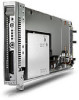
5 Connectors, Switches, and LEDs This chapter explains the location and function of system connectors, system switches, and internal and external LEDs. Connectors The figures and tables on the following pages show connector locations on the HP BladeSystem Blade PCs and HP BladeSystem PC Blade Enclosures. Enclosure Connectors This section explains the location and function of rear panel connectors associated with the HP PC Blade Switch and RJ-45 patch panel interconnect tray. Interconnect Switch Connectors Figure 5-1 HP PC Blade Switch connectors NOTE: bc2800 shown. Item (1) (2) (3) (4) Description Gigabit Ethernet jack for port 43 Socket for optional GBIC SFP module for port 43 Socket for optional GBIC SFP module for port 44 Gigabit Ethernet jack for port 44 30 Chapter 5 Connectors, Switches, and LEDs Location Interconnect switch Interconnect switch Interconnect switch Interconnect switch
-
 1
1 -
2
-
3
-
4
-
5
-
6
-
7
-
8
-
9
-
10
-
11
-
12
-
13
-
14
-
15
-
16
-
17
-
18
-
19
-
20
-
21
-
22
-
23
-
24
-
25
-
26
-
27
-
28
-
29
-
30
-
 31
31 -
 32
32 -
 33
33 -
 34
34 -
 35
35 -
 36
36 -
 37
37 -
 38
38 -
 39
39 -
 40
40 -
 41
41 -
42
-
43
-
44
-
45
-
46
-
47
-
48
-
49
-
50
-
51
-
52
-
53
-
54
-
55
-
56
-
57
-
58
-
59
-
60
-
61
-
62
-
63
-
64
-
65
-
66
-
67
-
68
-
69
-
70
-
71
-
72
-
73
-
74
-
75
-
76
-
77
-
78
-
79
 |
 |
