HP BladeSystem bc2800 Service Reference Guide: HP BladeSystem PC Blade Enclosu - Page 24
Non-Hot-Plug Procedures, Fan Cage
 |
View all HP BladeSystem bc2800 manuals
Add to My Manuals
Save this manual to your list of manuals |
Page 24 highlights
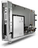
Non-Hot-Plug Procedures Before removing or replacing non-hot-plug components, you must power down the HP PC Blade Enclosure completely. Non-hot-plug components in the HP BladeSystem PC Blade Enclosure system include: ● Fan cage ● Fan backplane assembly ● Interconnect tray ● Integrated Administrator module ● Enclosure status assembly ● Midplane assembly Fan Cage To remove the fan cage: 1. Power down each HP Blade PC (Powering Down a Blade PC on page 12). 2. Power down the enclosure. For more information see the Powering Down the Enclosure on page 10. 3. Disconnect all cables and power cords from the AC power source. 4. Disconnect all cables and power cords from the enclosure rear panel. 5. Remove all HP Blade PCs (Removing a Blade PC on page 13). CAUTION: Integrated Administrator security settings are assigned to HP PC Blade Enclosure bays, not to HP Blade PCs. If HP Blade PCs change locations within the enclosure, Integrated Administrator settings must also be adjusted to ensure accurate security. Refer to the HP Integrated Administrator User Guide for more information on security settings. 6. Remove both hot-plug power supplies (Hot-Plug Power Supplies on page 8). 7. Remove the interconnect tray (Removing the Interconnect Tray on page 15). 8. Remove the enclosure from the rack (Removing the HP PC Blade Enclosure from the Rack on page 16). 9. Place the enclosure on a level, non-conductive surface. 10. Open the access door (1) (Opening the Access Door on page 17). 11. Press the fan cage release latch (2). 12. Pull the fan cage out of the enclosure until it locks in the open position (3). 13. Open the latches on the cable connector (4). 14. Disconnect the fan cable from the midplane (power board) (5). 15. Press the fan cage removal latch on top of the fan cage (6). 18 Chapter 3 Removal and Replacement Procedures
-
 1
1 -
2
-
3
-
4
-
5
-
6
-
7
-
8
-
9
-
10
-
11
-
12
-
13
-
14
-
15
-
16
-
17
-
18
-
 19
19 -
 20
20 -
 21
21 -
 22
22 -
 23
23 -
 24
24 -
 25
25 -
 26
26 -
 27
27 -
 28
28 -
 29
29 -
30
-
31
-
32
-
33
-
34
-
35
-
36
-
37
-
38
-
39
-
40
-
41
-
42
-
43
-
44
-
45
-
46
-
47
-
48
-
49
-
50
-
51
-
52
-
53
-
54
-
55
-
56
-
57
-
58
-
59
-
60
-
61
-
62
-
63
-
64
-
65
-
66
-
67
-
68
-
69
-
70
-
71
-
72
-
73
-
74
-
75
-
76
-
77
-
78
-
79
 |
 |
