HP BladeSystem bc2800 Service Reference Guide: HP BladeSystem PC Blade Enclosu - Page 35
Null-Modem Cable Pin-Out,
 |
View all HP BladeSystem bc2800 manuals
Add to My Manuals
Save this manual to your list of manuals |
Page 35 highlights
Figure 4-2 Installing a diagnostic adapter USB 2.0 version Table 4-3 Cable Pin Out for a Null Modem Cable Signal name EM PIN TxD 3 RxD 2 RTS 7 CTS 8 GND 5 DSR 6 CD 1 DB 9 PIN 2 3 8 7 5 4 4 DB 25 PIN 3 2 5 4 7 20 20 Null-Modem Cable Pin-Out Use the above table(s) to determine the specifications of the cable(s). If you are cabling a serial device (such as a laptop computer) to the console connector on the Integrated Administrator, be sure that you use a null-modem cable and not a straight-through cable. Hardware Diagnostic Tools 29
-
 1
1 -
2
-
3
-
4
-
5
-
6
-
7
-
8
-
9
-
10
-
11
-
12
-
13
-
14
-
15
-
16
-
17
-
18
-
19
-
20
-
21
-
22
-
23
-
24
-
25
-
26
-
27
-
28
-
29
-
 30
30 -
 31
31 -
 32
32 -
 33
33 -
 34
34 -
 35
35 -
 36
36 -
 37
37 -
 38
38 -
 39
39 -
 40
40 -
41
-
42
-
43
-
44
-
45
-
46
-
47
-
48
-
49
-
50
-
51
-
52
-
53
-
54
-
55
-
56
-
57
-
58
-
59
-
60
-
61
-
62
-
63
-
64
-
65
-
66
-
67
-
68
-
69
-
70
-
71
-
72
-
73
-
74
-
75
-
76
-
77
-
78
-
79
 |
 |

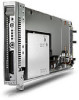
Figure 4-2
Installing a diagnostic adapter USB 2.0 version
Table 4-3
Cable Pin Out for a Null Modem Cable
Signal name
EM PIN
DB 9 PIN
DB 25 PIN
TxD
3
2
3
RxD
2
3
2
RTS
7
8
5
CTS
8
7
4
GND
5
5
7
DSR
6
4
20
CD
1
4
20
Null-Modem Cable Pin-Out
Use the above table(s) to determine the specifications of the cable(s). If you are cabling a serial
device (such as a laptop computer) to the console connector on the Integrated Administrator, be sure
that you use a null-modem cable and not a straight-through cable.
Hardware Diagnostic Tools
29