HP Carrier-grade cc3300 UserÆs Guide and Technical UserÆs Gu - Page 16
Chassis Feature Locations
 |
View all HP Carrier-grade cc3300 manuals
Add to My Manuals
Save this manual to your list of manuals |
Page 16 highlights
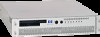
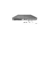
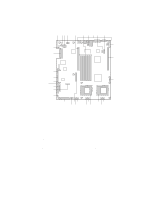
Chassis Feature Locations Front Panel Figure 2 shows the front panel view of the system. The front panel contains system control switches, alarm indicators and relays, and status indicators. You will find the front panel's controls summarized in Table 3. A NMI Switch G Alarm: PWR (green) B System Power Switch H Status: NIC (green) C System Reset I Status: DSK (HDD Activity, green) D Alarm: CRT (Critical) J Status: Main Power (green) E Alarm: MJR (Major) K Status: User ID (white) F Alarm: MNR (Minor) Figure 2. Front Panel Control Locations 16 cc2300 Carrier Grade Server Product Guide
-
 1
1 -
2
-
3
-
4
-
5
-
6
-
7
-
8
-
9
-
10
-
 11
11 -
 12
12 -
 13
13 -
 14
14 -
 15
15 -
 16
16 -
 17
17 -
 18
18 -
 19
19 -
 20
20 -
 21
21 -
22
-
23
-
24
-
25
-
26
-
27
-
28
-
29
-
30
-
31
-
32
-
33
-
34
-
35
-
36
-
37
-
38
-
39
-
40
-
41
-
42
-
43
-
44
-
45
-
46
-
47
-
48
-
49
-
50
-
51
-
52
-
53
-
54
-
55
-
56
-
57
-
58
-
59
-
60
-
61
-
62
-
63
-
64
-
65
-
66
-
67
-
68
-
69
-
70
-
71
-
72
-
73
-
74
-
75
-
76
-
77
-
78
-
79
-
80
-
81
-
82
-
83
-
84
-
85
-
86
-
87
-
88
-
89
-
90
-
91
-
92
-
93
-
94
-
95
-
96
-
97
-
98
-
99
-
100
-
101
-
102
-
103
-
104
-
105
-
106
-
107
-
108
-
109
-
110
-
111
-
112
-
113
-
114
-
115
-
116
-
117
-
118
-
119
-
120
-
121
-
122
-
123
-
124
-
125
-
126
-
127
-
128
-
129
-
130
-
131
-
132
-
133
-
134
-
135
 |
 |

16
cc2300 Carrier Grade Server Product Guide
Chassis Feature Locations
Front Panel
Figure 2 shows the front panel view of the system.
The front panel contains system control
switches, alarm indicators and relays, and status indicators.
You will find the front panel’s controls
summarized in Table 3.
A
NMI Switch
G
Alarm:
PWR (green)
B
System Power Switch
H
Status:
NIC (green)
C
System Reset
I
Status:
DSK (HDD Activity, green)
D
Alarm:
CRT (Critical)
J
Status:
Main Power (green)
E
Alarm:
MJR (Major)
K
Status:
User ID (white)
F
Alarm:
MNR (Minor)
Figure 2.
Front Panel Control Locations