HP Carrier-grade cc3300 UserÆs Guide and Technical UserÆs Gu - Page 17
Table 3., Front Panel Features
 |
View all HP Carrier-grade cc3300 manuals
Add to My Manuals
Save this manual to your list of manuals |
Page 17 highlights
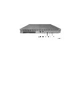
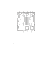
Table 3. Front Panel Features Item Feature Description Front Panel Switches A NMI switch A momentary switch used to instruct the processor to copy system memory to the hard drive. Pressing the recessed button with a paper clip or pin puts the server in a halt state for diagnostic purposes and allows you to issue a non•maskable interrupt. After issuing the interrupt, a memory dump can be performed to determine the cause of the problem. B Power switch Toggles the system power. C Reset switch Reboots and initializes the system. Front Panel Alarm LEDs and Relays D Critical (amber) When continuously lit, indicates the presence of a Critical System Fault. A critical system fault is an error or event detected by the system with a fatal impact to the system. In this case, the system cannot continue to operate. An example could be the loss of a large section of memory. Additionally, the front panel critical alarm relay will engage. E Major (amber) When continuously lit, indicates the presence of a Major System Fault. A major system fault is an error or event detected by the system that has discernable impact to system operation. In this case, the system can continue to operate but in a "degraded" fashion (reduced performance or loss of non-fatal feature reduction). An example could be the loss of one of two mirrored disks. Additionally, the front panel major alarm relay will engage. F Minor (amber) When continuously lit, indicates the presence of a Minor System Fault. A minor system fault is an error or event detected by the system but has little impact to actual system operation. An example would be a correctable ECC error. Additionally, the front panel minor alarm relay will engage. G Power (amber) When continuously lit indicates the presence of a Power System Fault. Additionally, the front panel power alarm relay will engage. Front Panel Status LEDs H NIC activity LED Indicates NIC activity. (green) I HDD activity Indicates any system SCSI hard drive activity. LED (green) J Main power When continuously lit, indicates the presence of DC power in the server. The LED (green) LED goes out when the power is turned off or the power source is disrupted. When it is blinking green, it indicates that the system is in ACPI sleep mode. K User ID (white) When continuously lit, indicates that the user ID function has been activated. Front Panel Connectors (Concealed by the Bezel) RJ45 Serial Connector Serial Connector (also available on the back panel through a second RJ45 connector). 2 x USB Connectors USB Port 2 and USB Port 3. cc2300 Carrier Grade Server Product Guide 17
-
 1
1 -
2
-
3
-
4
-
5
-
6
-
7
-
8
-
9
-
10
-
11
-
 12
12 -
 13
13 -
 14
14 -
 15
15 -
 16
16 -
 17
17 -
 18
18 -
 19
19 -
 20
20 -
 21
21 -
 22
22 -
23
-
24
-
25
-
26
-
27
-
28
-
29
-
30
-
31
-
32
-
33
-
34
-
35
-
36
-
37
-
38
-
39
-
40
-
41
-
42
-
43
-
44
-
45
-
46
-
47
-
48
-
49
-
50
-
51
-
52
-
53
-
54
-
55
-
56
-
57
-
58
-
59
-
60
-
61
-
62
-
63
-
64
-
65
-
66
-
67
-
68
-
69
-
70
-
71
-
72
-
73
-
74
-
75
-
76
-
77
-
78
-
79
-
80
-
81
-
82
-
83
-
84
-
85
-
86
-
87
-
88
-
89
-
90
-
91
-
92
-
93
-
94
-
95
-
96
-
97
-
98
-
99
-
100
-
101
-
102
-
103
-
104
-
105
-
106
-
107
-
108
-
109
-
110
-
111
-
112
-
113
-
114
-
115
-
116
-
117
-
118
-
119
-
120
-
121
-
122
-
123
-
124
-
125
-
126
-
127
-
128
-
129
-
130
-
131
-
132
-
133
-
134
-
135
 |
 |
