HP Carrier-grade cc3300 UserÆs Guide and Technical UserÆs Gu - Page 96
Serial Port Connector Back Panel
 |
View all HP Carrier-grade cc3300 manuals
Add to My Manuals
Save this manual to your list of manuals |
Page 96 highlights
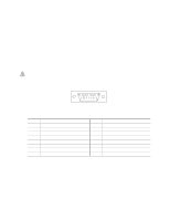
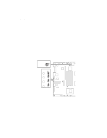
Serial Port Connector (Back Panel) An RJ45 connector on the back panel I/O supplies a serial interface (see Table 17). The interface may be used either as an emergency management port (EMP) or as a normal serial port. As an EMP, COM2 is used as a communication path by the server management software that provides a level of emergency management through an external modem. Table 17 describes the serial port's connections. If the system is configured for both back and front panel serial port operation, by default the back panel connector is enabled and the front panel connector is disabled. Plugging a cable into the front panel connector disables the back panel connector and enables the front panel connector (if pins 4 and 5 are connected together). Figure 31. Serial Port Connector The rear serial port is a fully functional COM port and will support any standard serial device as well as providing support for serial concentrators, which typically support RJ45 serial connectors. For those server applications that use a serial concentrator to access the server management features of the baseboard, a standard 8-pin CAT-5 cable from the serial concentrator is plugged directly into the rear RJ45 serial port. The 8 pins of the RJ45 connector can be configured to match either of two pin-out standards used by serial port concentrators. To accommodate either standard, the J6A2 jumper block, located directly behind the rear RJ45 serial port, must be jumpered appropriately according to the desired standard (see Figure 33). Table 17. Serial Port Connector Pinout Pin Signal 1 RTS 2 DTR 3 TXD 4 GND 5 RIA 6 RXD 7 DSR/DCD 8 CTS 1 Use jumper on server board to select Description Request to send Data terminal ready Transmit data Ground Ring indicator Receive data Date set ready / data carrier detect1 Clear to send NOTE By default as configured in the factory, the cc2300 Carrier Grade Server baseboard will have the rear RJ45 serial port configured to support a DSR signal. 96 cc2300 Carrier Grade Server Product Guide
-
 1
1 -
2
-
3
-
4
-
5
-
6
-
7
-
8
-
9
-
10
-
11
-
12
-
13
-
14
-
15
-
16
-
17
-
18
-
19
-
20
-
21
-
22
-
23
-
24
-
25
-
26
-
27
-
28
-
29
-
30
-
31
-
32
-
33
-
34
-
35
-
36
-
37
-
38
-
39
-
40
-
41
-
42
-
43
-
44
-
45
-
46
-
47
-
48
-
49
-
50
-
51
-
52
-
53
-
54
-
55
-
56
-
57
-
58
-
59
-
60
-
61
-
62
-
63
-
64
-
65
-
66
-
67
-
68
-
69
-
70
-
71
-
72
-
73
-
74
-
75
-
76
-
77
-
78
-
79
-
80
-
81
-
82
-
83
-
84
-
85
-
86
-
87
-
88
-
89
-
90
-
 91
91 -
 92
92 -
 93
93 -
 94
94 -
 95
95 -
 96
96 -
 97
97 -
 98
98 -
 99
99 -
 100
100 -
 101
101 -
102
-
103
-
104
-
105
-
106
-
107
-
108
-
109
-
110
-
111
-
112
-
113
-
114
-
115
-
116
-
117
-
118
-
119
-
120
-
121
-
122
-
123
-
124
-
125
-
126
-
127
-
128
-
129
-
130
-
131
-
132
-
133
-
134
-
135
 |
 |
