HP Carrier-grade cc3300 UserÆs Guide and Technical UserÆs Gu - Page 32
Introduction, Interface Requirements, Power Supply Module LED Indicators
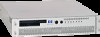 |
View all HP Carrier-grade cc3300 manuals
Add to My Manuals
Save this manual to your list of manuals |
Page 32 highlights
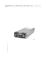
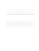
Introduction The DC version of the cc2300 Carrier Grade Server uses a -48 to -60 VDC input switching power subsystem, which provides up to 250 Watts with -48 to -60 VDC input and with current and remote sense regulation. Interface Requirements DC Input The DC power source may produce hazardous voltage levels exceeding -60 VDC and high energy levels above 240VA that may cause electric shock or burns. All DC input connections should be made only by a qualified service person only to prevent injury. All wiring terminals connected to the DC input terminal block must be fully-insulated with no exposed bare metal. DC Output Connectors The power subsystem DC power and control signals are interfaced to the server system via wire harnesses when the power supply modules are inserted into the power subsystem enclosure. The safety ground pin of the power supply module is the first pin to connect and the last to disconnect when the module is being inserted or removed from the power subsystem housing. In addition to the 5 V Standby, -12 V, +3.3 V, +5 V and +12 VDC outputs, the following signals and output pins are included: • +3.3 VDC remote sense • +5 VDC remote sense • +12 VDC remote sense • Remote sense return • Power Subsystem On (DC PWR enable) • Power Good • I2C* * PS Failure, PS Presence, PS Predictive Fail, +12 V Mon, +5 V Mon, and the 5 V Standby rails failure are being monitored via an I2C interface chip. Power Supply Module LED Indicators There is a single bi-color LED to indicate power supply status. When DC is applied to the PSU and standby voltages are available the LED blinks GREEN. The LED turns on GREEN to indicate that all the power outputs are available. The LED turns on AMBER to indicate that the power supply has failed, shutdown due to over current, shutdown due to over temperature, or is indicating a predictive failure. Refer to LED Indicators for conditions of the LEDs. The Alert signal from the Heceta-P will trigger an AMBER blinking LED condition. If the module condition is Alert and Fail at the same time, the LED will be AMBER with no blinking. The LED is visible on the power supply module's exterior surface at the back of the system. Table 8. LED Indicators Power Supply Condition No DC power to all PSU No DC power to this PSU only Power Supply LED OFF AMBER 32 cc2300 Carrier Grade Server Product Guide
-
 1
1 -
2
-
3
-
4
-
5
-
6
-
7
-
8
-
9
-
10
-
11
-
12
-
13
-
14
-
15
-
16
-
17
-
18
-
19
-
20
-
21
-
22
-
23
-
24
-
25
-
26
-
 27
27 -
 28
28 -
 29
29 -
 30
30 -
 31
31 -
 32
32 -
 33
33 -
 34
34 -
 35
35 -
 36
36 -
 37
37 -
38
-
39
-
40
-
41
-
42
-
43
-
44
-
45
-
46
-
47
-
48
-
49
-
50
-
51
-
52
-
53
-
54
-
55
-
56
-
57
-
58
-
59
-
60
-
61
-
62
-
63
-
64
-
65
-
66
-
67
-
68
-
69
-
70
-
71
-
72
-
73
-
74
-
75
-
76
-
77
-
78
-
79
-
80
-
81
-
82
-
83
-
84
-
85
-
86
-
87
-
88
-
89
-
90
-
91
-
92
-
93
-
94
-
95
-
96
-
97
-
98
-
99
-
100
-
101
-
102
-
103
-
104
-
105
-
106
-
107
-
108
-
109
-
110
-
111
-
112
-
113
-
114
-
115
-
116
-
117
-
118
-
119
-
120
-
121
-
122
-
123
-
124
-
125
-
126
-
127
-
128
-
129
-
130
-
131
-
132
-
133
-
134
-
135
 |
 |
