HP Carrier-grade cc3300 UserÆs Guide and Technical UserÆs Gu - Page 89
Upgrading the Chassis
 |
View all HP Carrier-grade cc3300 manuals
Add to My Manuals
Save this manual to your list of manuals |
Page 89 highlights
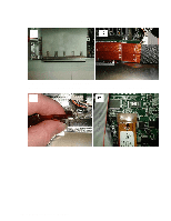
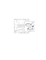
5 Upgrading the Chassis Replacing the Server Board The replacement server board comes already installed in a replacement chassis. Please note that warranty is tracked by the serial and product number on your original system. Please record the serial and product number of the original server you purchased and affix it to the replacement server. 1. Remove the top cover of the failed server. 2. Remove any PCI cards that may be installed in a 3.3 Volt or 5 Volt riser boards and place them on a clean, static-free surface. 3. Unplug the PCI riser boards from the server board and place them on a clean, static-free surface. 4. Remove the heatsink(s) and processor(s) from the server board and place them on a clean, static-free surface. 5. Remove the memory DIMMs from the server board and place them on a static-free surface. 6. Remove the disks and place them on a static-free surface. 7. Place the replacement server on a static-free surface and install components that were removed in steps 1 through 7. NOTE: Be sure to install the heat dissipation strip (powerstrate) between the processor and the heat sink. 8. Replace the top cover. Replacing the Front Panel Board To replace the front panel board, follow this procedure: 1. Disconnect the USB, alarms, and front panel signal cables (A in Figure 26) from the front panel board. 2. Remove the screw securing the front panel board to the front panel (B in Figure 26). 3. Slide the front panel board in the direction of the arrow (C in Figure 26) to release from the keyhole standoffs. 4. Lift out the front panel board and place it on a clean, static-free work surface. cc2300 Carrier Grade Server Product Guide 89
-
 1
1 -
2
-
3
-
4
-
5
-
6
-
7
-
8
-
9
-
10
-
11
-
12
-
13
-
14
-
15
-
16
-
17
-
18
-
19
-
20
-
21
-
22
-
23
-
24
-
25
-
26
-
27
-
28
-
29
-
30
-
31
-
32
-
33
-
34
-
35
-
36
-
37
-
38
-
39
-
40
-
41
-
42
-
43
-
44
-
45
-
46
-
47
-
48
-
49
-
50
-
51
-
52
-
53
-
54
-
55
-
56
-
57
-
58
-
59
-
60
-
61
-
62
-
63
-
64
-
65
-
66
-
67
-
68
-
69
-
70
-
71
-
72
-
73
-
74
-
75
-
76
-
77
-
78
-
79
-
80
-
81
-
82
-
83
-
 84
84 -
 85
85 -
 86
86 -
 87
87 -
 88
88 -
 89
89 -
 90
90 -
 91
91 -
 92
92 -
 93
93 -
 94
94 -
95
-
96
-
97
-
98
-
99
-
100
-
101
-
102
-
103
-
104
-
105
-
106
-
107
-
108
-
109
-
110
-
111
-
112
-
113
-
114
-
115
-
116
-
117
-
118
-
119
-
120
-
121
-
122
-
123
-
124
-
125
-
126
-
127
-
128
-
129
-
130
-
131
-
132
-
133
-
134
-
135
 |
 |
