HP Carrier-grade cc3300 UserÆs Guide and Technical UserÆs Gu - Page 75
Adding a Processor
 |
View all HP Carrier-grade cc3300 manuals
Add to My Manuals
Save this manual to your list of manuals |
Page 75 highlights
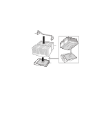
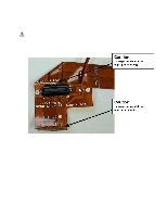
Adding a Processor If you are adding a second processor to your system, you must first remove the terminator from the secondary processor socket. The second processor must be compatible with the first processor (within one stepping, same voltage, and same speed.). 1. Observe the safety and ESD precautions at the beginning of this chapter. 2. Remove the top cover. 3. Remove any PCI cards that may obscure the processors. 4. Raise the locking bar on the processor socket and remove the terminator as shown in Figure 18. OM11814 Figure 18. Raising the Locking Bar and Removing the Terminator cc2300 Carrier Grade Server Product Guide 75
-
 1
1 -
2
-
3
-
4
-
5
-
6
-
7
-
8
-
9
-
10
-
11
-
12
-
13
-
14
-
15
-
16
-
17
-
18
-
19
-
20
-
21
-
22
-
23
-
24
-
25
-
26
-
27
-
28
-
29
-
30
-
31
-
32
-
33
-
34
-
35
-
36
-
37
-
38
-
39
-
40
-
41
-
42
-
43
-
44
-
45
-
46
-
47
-
48
-
49
-
50
-
51
-
52
-
53
-
54
-
55
-
56
-
57
-
58
-
59
-
60
-
61
-
62
-
63
-
64
-
65
-
66
-
67
-
68
-
69
-
 70
70 -
 71
71 -
 72
72 -
 73
73 -
 74
74 -
 75
75 -
 76
76 -
 77
77 -
 78
78 -
 79
79 -
 80
80 -
81
-
82
-
83
-
84
-
85
-
86
-
87
-
88
-
89
-
90
-
91
-
92
-
93
-
94
-
95
-
96
-
97
-
98
-
99
-
100
-
101
-
102
-
103
-
104
-
105
-
106
-
107
-
108
-
109
-
110
-
111
-
112
-
113
-
114
-
115
-
116
-
117
-
118
-
119
-
120
-
121
-
122
-
123
-
124
-
125
-
126
-
127
-
128
-
129
-
130
-
131
-
132
-
133
-
134
-
135
 |
 |

cc2300 Carrier Grade Server Product Guide
75
Adding a Processor
If you are adding a second processor to your system, you must first remove the terminator from the
secondary processor socket.
The second processor must be compatible with the first processor
(within one stepping, same voltage, and same speed.).
1.
Observe the safety and ESD precautions at the beginning of this chapter.
2.
Remove the top cover.
3.
Remove any PCI cards that may obscure the processors.
4.
Raise the locking bar on the processor socket and remove the terminator as shown in Figure 18.
OM11814
Figure 18.
Raising the Locking Bar and Removing the Terminator