HP Carrier-grade cc3300 UserÆs Guide and Technical UserÆs Gu - Page 36
Cooling Subsystem
 |
View all HP Carrier-grade cc3300 manuals
Add to My Manuals
Save this manual to your list of manuals |
Page 36 highlights
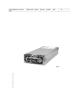
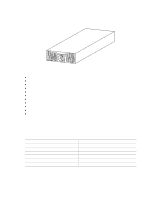
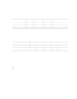
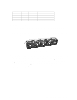
Cc2300 Internal Disk Drive Product Numbers Product Number Disk Capacity Rotational speed Disk Replacement Part Number A6917A 18 GB 10,000 RPM A6917-69001 A6942A 18 GB 15,000 RPM A6942-69001 A6918A 36GB 10,000 RPM A6918-69001 A6943A 36 GB 15,000 RPM A6943-69001 Cooling Subsystem The cooling subsystem contains a fan module consisting of five 40 mm fans to cool the server board and other components. The fans are installed directly behind the drive tray and are located in front of the server board. The fan connector is located on the server board. Each fan provides tachometer signal output to the server board to indicate a fan failure. A fan failure is indicated by the fan fault LED located on the front panel. The fan module is shown in Figure 10. Figure 10. Fan Module Ambient Temperature Control The system baseboard contains a pulse-width-modulation (PWM) circuit, which cycles the 12 VDC fan voltage to provide quiet operation when system baseboard temperature is low and there are no fan failures. Under normal baseboard temperature conditions (less than 45 °C), the fan power circuit supplies an effective fan voltage of 7.0 VDC. When the baseboard temperature exceeds 45 °C, the fan control circuit ceases cycling and delivers 12 VDC. Following a baseboard temperature excursion above 45 °C the fan voltage does not reenter PWM mode until the baseboard temperature drops below 45 °C and all fans are operational. 36 cc2300 Carrier Grade Server Product Guide
-
 1
1 -
2
-
3
-
4
-
5
-
6
-
7
-
8
-
9
-
10
-
11
-
12
-
13
-
14
-
15
-
16
-
17
-
18
-
19
-
20
-
21
-
22
-
23
-
24
-
25
-
26
-
27
-
28
-
29
-
30
-
 31
31 -
 32
32 -
 33
33 -
 34
34 -
 35
35 -
 36
36 -
 37
37 -
 38
38 -
 39
39 -
 40
40 -
 41
41 -
42
-
43
-
44
-
45
-
46
-
47
-
48
-
49
-
50
-
51
-
52
-
53
-
54
-
55
-
56
-
57
-
58
-
59
-
60
-
61
-
62
-
63
-
64
-
65
-
66
-
67
-
68
-
69
-
70
-
71
-
72
-
73
-
74
-
75
-
76
-
77
-
78
-
79
-
80
-
81
-
82
-
83
-
84
-
85
-
86
-
87
-
88
-
89
-
90
-
91
-
92
-
93
-
94
-
95
-
96
-
97
-
98
-
99
-
100
-
101
-
102
-
103
-
104
-
105
-
106
-
107
-
108
-
109
-
110
-
111
-
112
-
113
-
114
-
115
-
116
-
117
-
118
-
119
-
120
-
121
-
122
-
123
-
124
-
125
-
126
-
127
-
128
-
129
-
130
-
131
-
132
-
133
-
134
-
135
 |
 |
