HP ENVY 15-bp100 Maintenance and Service Guide - Page 38
Removal and replacement procedures, Bottom cover
 |
View all HP ENVY 15-bp100 manuals
Add to My Manuals
Save this manual to your list of manuals |
Page 38 highlights
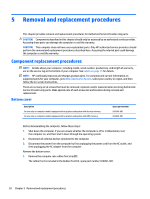
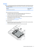
5 Removal and replacement procedures This chapter provides removal and replacement procedures for Authorized Service Provider only parts. CAUTION: Components described in this chapter should only be accessed by an authorized service provider. Accessing these parts can damage the computer or void the warranty. CAUTION: This computer does not have user-replaceable parts. Only HP authorized service providers should perform the removal and replacement procedures described here. Accessing the internal part could damage the computer or void the warranty. Component replacement procedures NOTE: Details about your computer, including model, serial number, product key, and length of warranty, are on the service tag at the bottom of your computer. See Labels on page 15 for details. NOTE: HP continually improves and changes product parts. For complete and current information on supported parts for your computer, go to http://partsurfer.hp.com, select your country or region, and then follow the on-screen instructions. There are as many as 55 screws that must be removed, replaced, and/or loosened when servicing Authorized Service Provider only parts. Make special note of each screw size and location during removal and replacement. Bottom cover Description For use only on computer models equipped with a graphics subsystem with discrete memory For use only on computer models equipped with a graphics subsystem with UMA memory Spare part number 924345-001 934639-001 Before disassembling the computer, follow these steps: 1. Shut down the computer. If you are unsure whether the computer is off or in Hibernation, turn the computer on, and then shut it down through the operating system. 2. Disconnect all external devices connected to the computer. 3. Disconnect the power from the computer by first unplugging the power cord from the AC outlet, and then unplugging the AC adapter from the computer. Remove the bottom cover: 1. Remove the computer rear rubber foot strip (1). The rubber foot is included in the Rubber Foot Kit, spare part number 924891-001. 30 Chapter 5 Removal and replacement procedures
-
 1
1 -
2
-
3
-
4
-
5
-
6
-
7
-
8
-
9
-
10
-
11
-
12
-
13
-
14
-
15
-
16
-
17
-
18
-
19
-
20
-
21
-
22
-
23
-
24
-
25
-
26
-
27
-
28
-
29
-
30
-
31
-
32
-
 33
33 -
 34
34 -
 35
35 -
 36
36 -
 37
37 -
 38
38 -
 39
39 -
 40
40 -
 41
41 -
 42
42 -
 43
43 -
44
-
45
-
46
-
47
-
48
-
49
-
50
-
51
-
52
-
53
-
54
-
55
-
56
-
57
-
58
-
59
-
60
-
61
-
62
-
63
-
64
-
65
-
66
-
67
-
68
-
69
-
70
-
71
-
72
-
73
-
74
-
75
-
76
-
77
-
78
-
79
-
80
-
81
-
82
-
83
-
84
-
85
-
86
-
87
-
88
-
89
-
90
 |
 |