HP ENVY 15-bp100 Maintenance and Service Guide - Page 52
until it rests at an angle., by sliding it up and to the left at an angle.
 |
View all HP ENVY 15-bp100 manuals
Add to My Manuals
Save this manual to your list of manuals |
Page 52 highlights
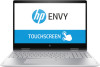
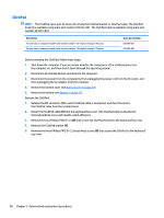
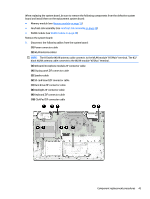
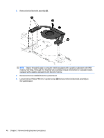
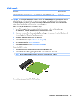
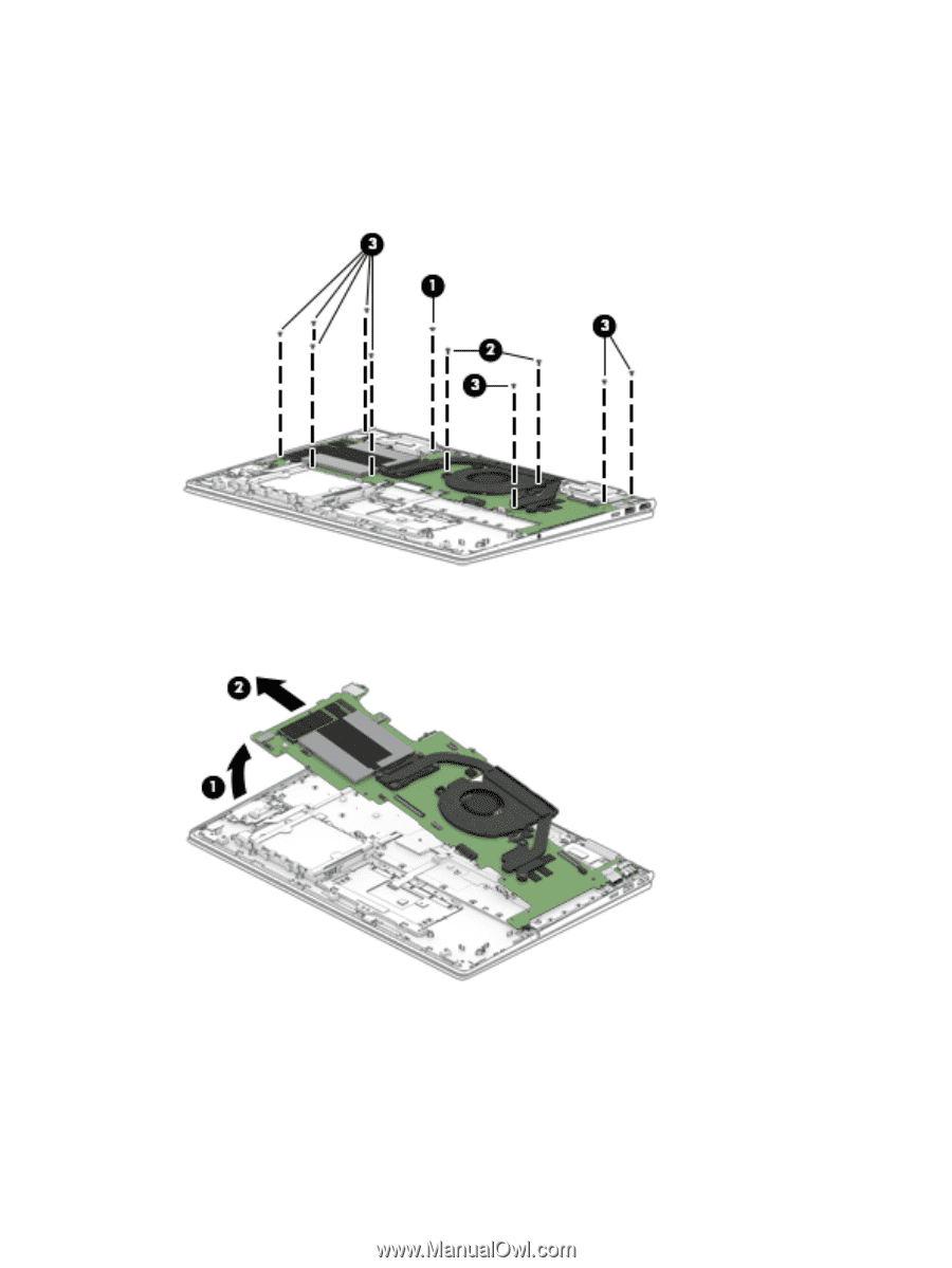
2. Remove the following screws: (1) One Phillips PM2.0×2.2 broad head screw that secures the WLAN module to the keyboard/top cover (2) Two Phillips PM2.0×4.6 screws that secure the system board to the keyboard/top cover (3) Eight Phillips PM2.0×3.3 screws that secure the system board to the keyboard/top cover 3. Lift the left side of the system board (1) until it rests at an angle. 4. Remove the system board (2) by sliding it up and to the left at an angle. Reverse this procedure to install the system board. 44 Chapter 5 Removal and replacement procedures
-
 1
1 -
2
-
3
-
4
-
5
-
6
-
7
-
8
-
9
-
10
-
11
-
12
-
13
-
14
-
15
-
16
-
17
-
18
-
19
-
20
-
21
-
22
-
23
-
24
-
25
-
26
-
27
-
28
-
29
-
30
-
31
-
32
-
33
-
34
-
35
-
36
-
37
-
38
-
39
-
40
-
41
-
42
-
43
-
44
-
45
-
46
-
 47
47 -
 48
48 -
 49
49 -
 50
50 -
 51
51 -
 52
52 -
 53
53 -
 54
54 -
 55
55 -
 56
56 -
 57
57 -
58
-
59
-
60
-
61
-
62
-
63
-
64
-
65
-
66
-
67
-
68
-
69
-
70
-
71
-
72
-
73
-
74
-
75
-
76
-
77
-
78
-
79
-
80
-
81
-
82
-
83
-
84
-
85
-
86
-
87
-
88
-
89
-
90
 |
 |
2.
Remove the following screws:
(1)
One Phillips PM2.0×2.2 broad head screw that secures the WLAN module to the keyboard/top cover
(2)
Two Phillips PM2.0×4.6 screws that secure the system board to the keyboard/top cover
(3)
Eight Phillips PM2.0×3.3 screws that secure the system board to the keyboard/top cover
3.
Lift the left side of the system board
(1)
until it rests at an angle.
4.
Remove the system board
(2)
by sliding it up and to the left at an angle.
Reverse this procedure to install the system board.
44
Chapter 5
Removal and replacement procedures