HP ENVY 15-bp100 Maintenance and Service Guide - Page 51
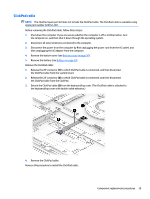
SD card board ZIF connector cable, Speaker cable
 |
View all HP ENVY 15-bp100 manuals
Add to My Manuals
Save this manual to your list of manuals |
Page 51 highlights
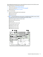
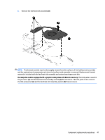
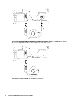
When replacing the system board, be sure to remove the following components from the defective system board and install them on the replacement system board: ● Memory module (see Memory module on page 35) ● Fan/heat sink assembly (see Fan/heat sink assembly on page 45) ● WLAN module (see WLAN module on page 49) Remove the system board: 1. Disconnect the following cables from the system board: (1) Power connector cable (2) WLAN antenna cables NOTE: The #1/white WLAN antenna cable connects to the WLAN module "#1/Main" terminal. The #2/ black WLAN antenna cable connects to the WLAN module "#2/Aux" terminal. (3) Webcam/microphone module ZIF connector cable (4) Display panel ZIF connector cable (5) Speaker cable (6) SD card board ZIF connector cable (7) Hard drive ZIF connector cable (8) Backlight ZIF connector cable (9) Keyboard ZIF connector cable (10) ClickPad ZIF connector cable Component replacement procedures 43
-
 1
1 -
2
-
3
-
4
-
5
-
6
-
7
-
8
-
9
-
10
-
11
-
12
-
13
-
14
-
15
-
16
-
17
-
18
-
19
-
20
-
21
-
22
-
23
-
24
-
25
-
26
-
27
-
28
-
29
-
30
-
31
-
32
-
33
-
34
-
35
-
36
-
37
-
38
-
39
-
40
-
41
-
42
-
43
-
44
-
45
-
 46
46 -
 47
47 -
 48
48 -
 49
49 -
 50
50 -
 51
51 -
 52
52 -
 53
53 -
 54
54 -
 55
55 -
 56
56 -
57
-
58
-
59
-
60
-
61
-
62
-
63
-
64
-
65
-
66
-
67
-
68
-
69
-
70
-
71
-
72
-
73
-
74
-
75
-
76
-
77
-
78
-
79
-
80
-
81
-
82
-
83
-
84
-
85
-
86
-
87
-
88
-
89
-
90
 |
 |