HP ENVY 15-bp100 Maintenance and Service Guide - Page 53
Fan/heat sink assembly
 |
View all HP ENVY 15-bp100 manuals
Add to My Manuals
Save this manual to your list of manuals |
Page 53 highlights
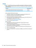
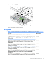
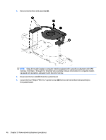
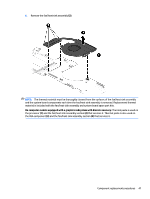
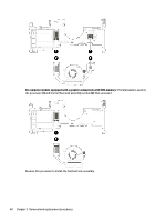
Fan/heat sink assembly NOTE: The fan/heat sink assembly spare part kit includes replacement thermal material. Description Spare part number For use only on computer models equipped with an Intel Core i7-8550U or Intel Core i5-8250U processor 936170-001 and a graphics subsystem with discrete memory For use only on computer models equipped with an Intel Core i7-8550U or or Intel Core i5-8250U processor and a graphics subsystem with UMA memory 936169-001 For use only on computer models equipped with an Intel Core i7-7500U or Intel Core i5-7200U processor 924349-001 and a graphics subsystem with discrete memory For use only on computer models equipped with an Intel Core i7-7500U or Intel Core i5-7200U processor 924348-001 and a graphics subsystem with UMA memory Before removing the fan/heat sink assembly, follow these steps: 1. Turn off the computer. If you are unsure whether the computer is off or in Hibernation, turn the computer on, and then shut it down through the operating system. 2. Disconnect the power from the computer by first unplugging the power cord from the AC outlet, and then unplugging the AC adapter from the computer. 3. Disconnect all external devices from the computer. 4. Remove the bottom cover (see Bottom cover on page 30). 5. Remove the battery (see Battery on page 32). 6. Remove the system board (see System board on page 41). Remove the fan/heat sink assembly: NOTE: Steps 1 through 3 apply to computer models equipped with a graphics subsystem with discrete memory. See Steps 4 through 6 for fan/heat sink assembly removal information for computer models equipped with a graphics subsystem with UMA memory. 1. Disconnect the fan cable (1) from the system board. 2. Loosen the six Phillips PM2.0×6.2 captive screws (2) that secure the fan/heat sink assembly to the system board. Component replacement procedures 45
-
 1
1 -
2
-
3
-
4
-
5
-
6
-
7
-
8
-
9
-
10
-
11
-
12
-
13
-
14
-
15
-
16
-
17
-
18
-
19
-
20
-
21
-
22
-
23
-
24
-
25
-
26
-
27
-
28
-
29
-
30
-
31
-
32
-
33
-
34
-
35
-
36
-
37
-
38
-
39
-
40
-
41
-
42
-
43
-
44
-
45
-
46
-
47
-
 48
48 -
 49
49 -
 50
50 -
 51
51 -
 52
52 -
 53
53 -
 54
54 -
 55
55 -
 56
56 -
 57
57 -
 58
58 -
59
-
60
-
61
-
62
-
63
-
64
-
65
-
66
-
67
-
68
-
69
-
70
-
71
-
72
-
73
-
74
-
75
-
76
-
77
-
78
-
79
-
80
-
81
-
82
-
83
-
84
-
85
-
86
-
87
-
88
-
89
-
90
 |
 |