HP ENVY 15-bp100 Maintenance and Service Guide - Page 58
SD card board, Remove the bottom cover see
 |
View all HP ENVY 15-bp100 manuals
Add to My Manuals
Save this manual to your list of manuals |
Page 58 highlights
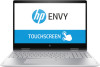
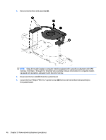
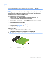
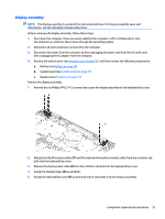
SD card board NOTE: The SD card board includes the power light actuator, hard drive light actuator, card reader slot, and SD card. The SD card board spare kit does not include the SD card board cable. The SD card board cable is available using spare part number 924325-001. Description For use only on computer models with model numbers 15m-bp1xx through 15-bp1xx equipped with a graphics subsystem with discrete memory For use only on computer models with model numbers 15m-bp1xx through 15-bp1xx equipped with a graphics subsystem with UMA memory For use only on computer models with model numbers 15m-bp0xx through 15-bp0xx Spare part number L01821-001 L01917-001 924336-001 Before removing the SD card board, follow these steps: 1. Shut down the computer. If you are unsure whether the computer is off or in Hibernation, turn the computer on, and then shut it down through the operating system. 2. Disconnect all external devices connected to the computer. 3. Disconnect the power from the computer by first unplugging the power cord from the AC outlet, and then unplugging the AC adapter from the computer. 4. Remove the bottom cover (see Bottom cover on page 30). 5. Remove the battery (see Battery on page 32). 6. Remove the system board (see System board on page 41). Remove the SD card board: 1. Remove the two Phillips PM2.0×3.3 screws (1) that secure the SD card board to the keyboard/top cover. 50 Chapter 5 Removal and replacement procedures
-
 1
1 -
2
-
3
-
4
-
5
-
6
-
7
-
8
-
9
-
10
-
11
-
12
-
13
-
14
-
15
-
16
-
17
-
18
-
19
-
20
-
21
-
22
-
23
-
24
-
25
-
26
-
27
-
28
-
29
-
30
-
31
-
32
-
33
-
34
-
35
-
36
-
37
-
38
-
39
-
40
-
41
-
42
-
43
-
44
-
45
-
46
-
47
-
48
-
49
-
50
-
51
-
52
-
 53
53 -
 54
54 -
 55
55 -
 56
56 -
 57
57 -
 58
58 -
 59
59 -
 60
60 -
 61
61 -
 62
62 -
 63
63 -
64
-
65
-
66
-
67
-
68
-
69
-
70
-
71
-
72
-
73
-
74
-
75
-
76
-
77
-
78
-
79
-
80
-
81
-
82
-
83
-
84
-
85
-
86
-
87
-
88
-
89
-
90
 |
 |