HP ENVY 15-bp100 Maintenance and Service Guide - Page 54
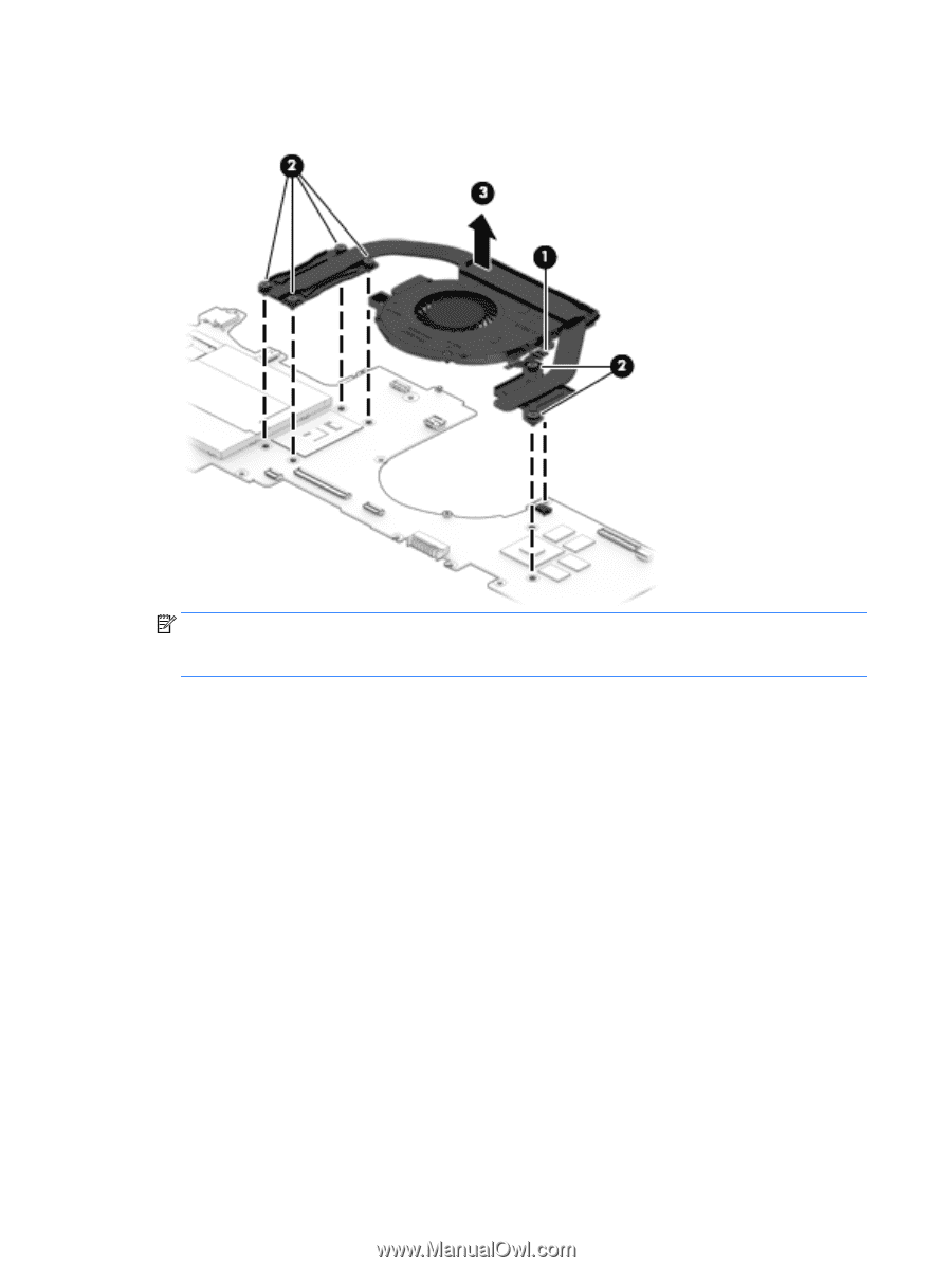
Loosen the four Phillips PM2.0×6.2 captive screws, that secure the fan/heat sink assembly
 |
View all HP ENVY 15-bp100 manuals
Add to My Manuals
Save this manual to your list of manuals |
Page 54 highlights
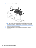
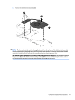
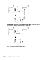
3. Remove the fan/heat sink assembly (3). NOTE: Steps 4 through 6 apply to computer models equipped with a graphics subsystem with UMA memory. See Steps 1 through 3 for fan/heat sink assembly removal information for computer models equipped with a graphics subsystem with discrete memory. 4. Disconnect the fan cable (1) from the system board. 5. Loosen the four Phillips PM2.0×6.2 captive screws (2) that secure the fan/heat sink assembly to the system board. 46 Chapter 5 Removal and replacement procedures
-
 1
1 -
2
-
3
-
4
-
5
-
6
-
7
-
8
-
9
-
10
-
11
-
12
-
13
-
14
-
15
-
16
-
17
-
18
-
19
-
20
-
21
-
22
-
23
-
24
-
25
-
26
-
27
-
28
-
29
-
30
-
31
-
32
-
33
-
34
-
35
-
36
-
37
-
38
-
39
-
40
-
41
-
42
-
43
-
44
-
45
-
46
-
47
-
48
-
 49
49 -
 50
50 -
 51
51 -
 52
52 -
 53
53 -
 54
54 -
 55
55 -
 56
56 -
 57
57 -
 58
58 -
 59
59 -
60
-
61
-
62
-
63
-
64
-
65
-
66
-
67
-
68
-
69
-
70
-
71
-
72
-
73
-
74
-
75
-
76
-
77
-
78
-
79
-
80
-
81
-
82
-
83
-
84
-
85
-
86
-
87
-
88
-
89
-
90
 |
 |
3.
Remove the fan/heat sink assembly
(3)
.
NOTE:
Steps 4 through 6 apply to computer models equipped with a graphics subsystem with UMA
memory. See Steps 1 through 3 for fan/heat sink assembly removal information for computer models
equipped with a graphics subsystem with discrete memory.
4.
Disconnect the fan cable
(1)
from the system board.
5.
Loosen the four Phillips PM2.0×6.2 captive screws
(2)
that secure the fan/heat sink assembly to
the system board.
46
Chapter 5
Removal and replacement procedures