HP ENVY 15-bp100 Maintenance and Service Guide - Page 68
from the display back cover. The wireless antenna
 |
View all HP ENVY 15-bp100 manuals
Add to My Manuals
Save this manual to your list of manuals |
Page 68 highlights
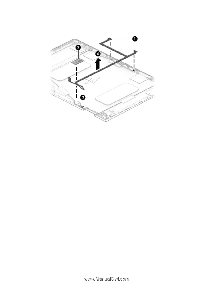
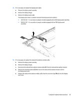
f. Detach the webcam/microphone module cable (4) from the display back cover. (The webcam/ microphone module cable is attached to the display back cover with double-sided adhesive.) g. Remove the webcam/microphone module cable. The webcam/microphone module cable is available using spare part number 924324-001. 14. If it is necessary to replace the wireless antenna cables and transceivers: a. Remove the display panel assembly. b. Remove the display hinges. c. Detach the wireless antenna transceivers (1) from the display back cover. (The wireless antenna transceivers are attached to the display back cover with double-sided adhesive.) d. Detach the four pieces of grounding tape (2) that secure the wireless antenna cables to the display back cover. e. Release the wireless antenna cables from the retention clips (3) built into the bottom edge of the display back cover. 60 Chapter 5 Removal and replacement procedures
-
 1
1 -
2
-
3
-
4
-
5
-
6
-
7
-
8
-
9
-
10
-
11
-
12
-
13
-
14
-
15
-
16
-
17
-
18
-
19
-
20
-
21
-
22
-
23
-
24
-
25
-
26
-
27
-
28
-
29
-
30
-
31
-
32
-
33
-
34
-
35
-
36
-
37
-
38
-
39
-
40
-
41
-
42
-
43
-
44
-
45
-
46
-
47
-
48
-
49
-
50
-
51
-
52
-
53
-
54
-
55
-
56
-
57
-
58
-
59
-
60
-
61
-
62
-
 63
63 -
 64
64 -
 65
65 -
 66
66 -
 67
67 -
 68
68 -
 69
69 -
 70
70 -
 71
71 -
 72
72 -
 73
73 -
74
-
75
-
76
-
77
-
78
-
79
-
80
-
81
-
82
-
83
-
84
-
85
-
86
-
87
-
88
-
89
-
90
 |
 |