HP EliteBook Folio 1000 HP EliteBook Folio 1040 G1 Notebook PC Maintenance and - Page 42
Lift the tape that secure the display cable connector on the panel, onto the keyboard.
 |
View all HP EliteBook Folio 1000 manuals
Add to My Manuals
Save this manual to your list of manuals |
Page 42 highlights
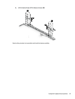
a. Remove the four Phillips PM2.0×2.0 screws that secure the display panel to the display enclosure. ● 739582-001 - 35.6-cm (14.0-in), LED, AntiGlare display panel, UWVA ● 739581-001 - 35.6-cm (14.0-in), LED, AntiGlare display panel, SVA HD+ b. Rotate the top of the display panel downward (1) onto the keyboard. c. Lift the tape that secure the display cable connector on the panel (2), and then disconnect the cable from the connector (3). Reverse this procedure to reassemble and install the display assembly components. 34 Chapter 5 Removal and replacement procedures for Authorized Service Provider parts
-
 1
1 -
2
-
3
-
4
-
5
-
6
-
7
-
8
-
9
-
10
-
11
-
12
-
13
-
14
-
15
-
16
-
17
-
18
-
19
-
20
-
21
-
22
-
23
-
24
-
25
-
26
-
27
-
28
-
29
-
30
-
31
-
32
-
33
-
34
-
35
-
36
-
 37
37 -
 38
38 -
 39
39 -
 40
40 -
 41
41 -
 42
42 -
 43
43 -
 44
44 -
 45
45 -
 46
46 -
 47
47 -
48
-
49
-
50
-
51
-
52
-
53
-
54
-
55
-
56
-
57
-
58
-
59
-
60
-
61
-
62
-
63
-
64
-
65
-
66
-
67
-
68
-
69
-
70
-
71
-
72
-
73
-
74
-
75
-
76
-
77
-
78
-
79
-
80
-
81
-
82
-
83
-
84
-
85
-
86
-
87
-
88
-
89
-
90
-
91
-
92
-
93
-
94
-
95
-
96
-
97
-
98
-
99
-
100
-
101
-
102
-
103
-
104
-
105
-
106
-
107
-
108
-
109
-
110
-
111
-
112
-
113
-
114
-
115
-
116
-
117
-
118
-
119
-
120
-
121
-
122
-
123
-
124
 |
 |

a.
Remove the four Phillips PM2.0×2.0 screws that secure the display panel to the display enclosure.
●
739582-001 — 35.6-cm (14.0-in), LED, AntiGlare display panel, UWVA
●
739581-001 — 35.6-cm (14.0-in), LED, AntiGlare display panel, SVA HD+
b.
Rotate the top of the display panel downward
(1)
onto the keyboard.
c.
Lift the tape that secure the display cable connector on the panel
(2)
, and then disconnect the
cable from the connector
(3)
.
Reverse this procedure to reassemble and install the display assembly components.
34
Chapter 5
Removal and replacement procedures for Authorized Service Provider parts