HP EliteBook Folio 1000 HP EliteBook Folio 1040 G1 Notebook PC Maintenance and - Page 70
by callout, To remove the system board
 |
View all HP EliteBook Folio 1000 manuals
Add to My Manuals
Save this manual to your list of manuals |
Page 70 highlights
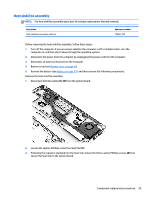
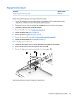
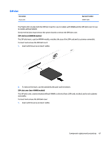
1. Disconnect the following cables: ● (1): Power connector ● (2): Speaker ● (3): Display panel ● (4): NFC module cable ● (5): Fingerprint reader ● (6): RTC battery ● (7): Multi-function board 2. Remove the four Phillips PM2.0×3.0 screws that secure the system board to the computer. 3. To remove the system board, be sure to lift near the middle of the board near the connectors as shown by callout (1) in the following image. CAUTION: To avoid damaging or breaking the system board, when removing the board, lift up near the middle of the board. Do not lift up on the narrow end of the board. 4. Lift the right side of the system board up at an angle (2). 62 Chapter 5 Removal and replacement procedures for Authorized Service Provider parts
-
 1
1 -
2
-
3
-
4
-
5
-
6
-
7
-
8
-
9
-
10
-
11
-
12
-
13
-
14
-
15
-
16
-
17
-
18
-
19
-
20
-
21
-
22
-
23
-
24
-
25
-
26
-
27
-
28
-
29
-
30
-
31
-
32
-
33
-
34
-
35
-
36
-
37
-
38
-
39
-
40
-
41
-
42
-
43
-
44
-
45
-
46
-
47
-
48
-
49
-
50
-
51
-
52
-
53
-
54
-
55
-
56
-
57
-
58
-
59
-
60
-
61
-
62
-
63
-
64
-
 65
65 -
 66
66 -
 67
67 -
 68
68 -
 69
69 -
 70
70 -
 71
71 -
 72
72 -
 73
73 -
 74
74 -
 75
75 -
76
-
77
-
78
-
79
-
80
-
81
-
82
-
83
-
84
-
85
-
86
-
87
-
88
-
89
-
90
-
91
-
92
-
93
-
94
-
95
-
96
-
97
-
98
-
99
-
100
-
101
-
102
-
103
-
104
-
105
-
106
-
107
-
108
-
109
-
110
-
111
-
112
-
113
-
114
-
115
-
116
-
117
-
118
-
119
-
120
-
121
-
122
-
123
-
124
 |
 |

1.
Disconnect the following cables:
●
(1)
: Power connector
●
(2)
: Speaker
●
(3)
: Display panel
●
(4)
: NFC module cable
●
(5)
: Fingerprint reader
●
(6)
: RTC battery
●
(7)
: Multi-function board
2.
Remove the four Phillips PM2.0×3.0 screws that secure the system board to the computer.
3.
To remove the system board, be sure to lift near the middle of the board near the connectors as shown
by callout
(1)
in the following image.
CAUTION:
To avoid damaging or breaking the system board, when removing the board, lift up near the
middle of the board. Do not lift up on the narrow end of the board.
4.
Lift the right side of the system board up at an angle
(2)
.
62
Chapter 5
Removal and replacement procedures for Authorized Service Provider parts